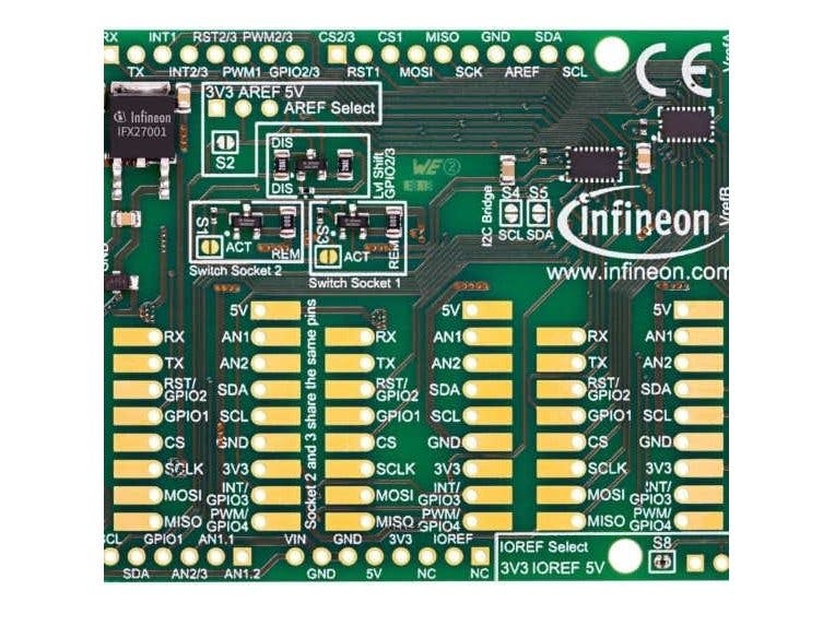
The MyIoT adapter acts as a gateway to connect Shield2Go and Kit2Go boards to hardware solutions using one of the most famous platforms for evaluation and prototyping - the Arduino Uno form factor.E.g. evaluation boards such as the Arduino Uno, XMC1100 Boot Kit or the XMC4700 Relax Kit for 5V Shields etc.
For an Arduino Board a supply voltage of 5.0 V is usually used as common voltage for the shields compatible with it. The MyIoT Adapter is equipped with an IFX27001 which is responsible for the level shifting to convert the logic level from 5.0 V to the 3.3 V of the Shields2Go. This level shifting can also be deactivated selectively by the corresponding solder bridges as shown in the picture below.
ATTENTION: Do not try to somehow connect the Shields2Go directly with an Arduino Uno without proper level shifting.
This Shield2Go adapter for Arduino also supports seperate power control of the Sockets 1 and 2; this means both can be switched on and off. As you can see on the adapter itself Socket 1 is marked independently with a square, while Socket 2 and Socket 3 share the same square, representing the fact that they also share the same pins to the underlying control Board.
Pin Layout for the MyIoT AdapterYou can find the original Image and also a quick starter guide for the adapter here.
ExampleTo have a better look how the Shield2Go adapter works, a quick example will be demontstrated below by using the DPS310 Shield2Go (Digital Pressure Sensor) and the TLV493D Shield2Go (3D Magnetic Sensor). The DPS310 was stacked on Socket 1 and the TLV493DShield on Socket 2 of the MyIoT Adapter. The whole adapter was then stacked on an Arduino Mega 2560, which also has an operating voltage of 5.0 V (can also be stacked on an Arduino and etc.) as depicted below:
To see that they're actually communicating and working with the Arduino Board we will go through the following steps.
1) If you don't have the Arduino IDE installed, you can download and install it from here.
Open the Arduino IDE and connect the Arduino with your PC using a USB Cable.
Click on the "Tools" dropdown menu and hover over "Board" and select your Board. Then hover over "Port" and select which Port you are connected to.
Hint: If you're using an XMC Board (e.g XMC4700 Relax Kit), please follow the installation and setup instructions here.
2) In the Arduino IDE navigate to "Tools>ManageLibraries..." and install the libraries in the picture below.
3) Navigate to "File>Examples>DigitalPressureSensnor>i2c_command" a new Arduino IDE window should pop up. In this new window verify the code, upload it on the Arduino and open up the serial monitor from the Tools dropdown menu voilà. Now you can read temprature and Air pressure. Now the DPS310 is also famous for its precision try moving the whole Board up and down and observe the change of pressure from the serial monitor.
NOTE: The DPS310 also has an SPI version, so make sure the I2C one is being used like the one in the example. But there also SPI Examples included in the DigitalPressureSensor library. (How do you know which version of the Pressure Shield2Go do you have ? Click here and jump to page 4 )
So now we've tested one Shield2Go, the DPS310. Let's test both at the same time.
4) In the Arduino IDE navigate to "File>Examples>TLV493D-A1B6>Cartesian". A new window should also pop up with the TLV493D Shield2Go example.
Now copy both examples (the i2c_background and the Cartesian) and paste them in another file and save the changes.
The arduino works with only one void setup() and void loop() function. So copy the contents of the voidsetup() and thevoidloop() and paste them in to the first setup() and loop() functions respectively and just add some delay between them for example 1s.
delay(1000); //add 1000 ms = 1 s delayAnd whatever was before those functions place them on the very top of the code. You're code should look something like the one attached.
5) Verify and upload your Code on the Arduino Board and open up the serial monitor to view the results. You can test the TLV493D Shield2Go by playing with a magnet around the TLV439D-A-1B6 chip and notice the change of values on the serial monitor. It should look something like this:
Voilà, there you have it. Plug and Play as easy as it gets !


_ztBMuBhMHo.jpg?auto=compress%2Cformat&w=48&h=48&fit=fill&bg=ffffff)


Comments
Please log in or sign up to comment.