

Hardware components | ||||||
 |
| × | 1 | |||
| × | 1 | ||||
| × | 1 | ||||
| × | 2 | ||||
| × | 1 | ||||
| × | 1 | ||||
Software apps and online services | ||||||
 |
| |||||
Hand tools and fabrication machines | ||||||
 |
| |||||
 |
| |||||
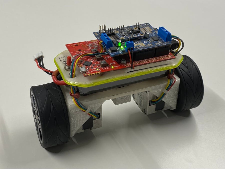
We built this self stabalizing robot as a base setup to show how robots will interact with their sourrunding based on different sensor types.
In this example you can see the robot equipped with a 24GHz radar and an ultrasonic sensor:
The XMC4700 offers several unused communication interfaces to add different kind of sensors to your project.
Interested in building your own robot?Find instructions how to build it HERE.
1) MechanicsStart your build with the "Top PlateXMC4700" or "Top Plate XMC4700 electric wire". The electric wire version offers a surrounding notch for an electroluminescent wire.
This part fits a DCDC voltage converter (WE 173010578) from 12V battery voltage to 5V for our controller and a possible electroluminescence inverter.Further it keeps your cables in place and holds the robots main switch.
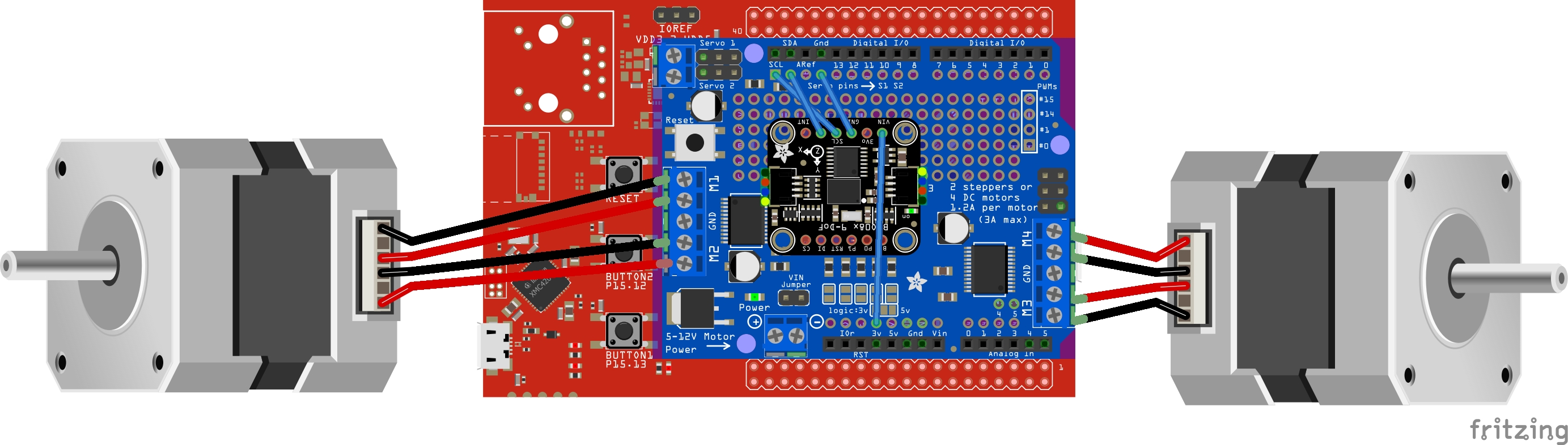
Screw the XMC4700 Relax Kit on top of it and stack the Motorshield on top of the microcontroller.The Motorshield offers an open area which is great to solder the IMU(inertial measurement unit) sensor right on top.
Continue with printing and assembly of the lower part - the chassis.It holds the two motors as well as the optional electroluminescence inverter.
Mount the top plate to the chassis using M3 spacers that matches your batterie height.
To connect wheels to the motors we used M5 spacers which we drilled out and added a thread to fix the wheel axle to the motor axle.
To attach the wheels to the wheel axle we printed another adaptor:
That's it - these are all parts you need to assemble your self-stabilized robot
This section gives you a short intro into the used electronic components. For a more detailed look check the supplier webpages.
Stepper Motors (Nema17) Steppers are important whenever you need to set an exact position. For such kind of robots that's not a must have but we used them to drive the robot back to its "home position" which is the starting point after you pushed it away.
Adafruit Motor/Stepper/Servo Shield for Arduino v2 This is the power stage to drive the motors. It's using TB6612 MOSFET drivers with 1.2A current capability per channel and comes with a handy Arduino library to drive stepper motors.
Elwire We use an electroluminescence (EL) wire to show the mode of our robot. It is a wire that you feed with AC voltage of about 100V and 2500Hz. This will let it glow all over its surface.
ELInverter To create the AC voltage for our EL wire an EL inverter is needed: Input 5V DC -> Output 100V AC
IMUBNO055 This sensor will help us to know the position of our robot and if it is about to fall to one side. For this we use: the Absolute Orientation (Euler Vector, 100Hz) Three axis orientation data based on a 360° sphere and the Angular Velocity Vector (100Hz) Three axis of 'rotation speed' in rad/s.
XMC4700RelaxKit the main controller and therefore the brain of our robot. It's featuring the Arduino Uno pinout and is enabled to be used in the Arduino IDE:
You can run the motors in four modes: Microstep (1/8), Interleave, Single and Double
Microstep (1/8) performs a smooth handover from one coil of the sepper to the other.This is the smoothest but also the slowest mode:
Interleave is only introducing a half step (1:2) during the handover from one coil to the other. This mode is faster than microstepping but not that smooth.
Double and Singlestep(1:1) are fulfilling a full step. While "single" mode is using only one coil as active one, "double" is using two active coils and has therefore more torque. These are the fastest modes but are also a bit rough at low speed.
The different speed ranges can be better seen in this graph:
To make full use of the stepper's capabilities in the different modes we use all of them by handing over from one to another:
Unfortunately this is a nightmare for any following control algorithm as for a different change of the control signal (x-axis) you see a different increase of speed value (y-axis).Thats why we linearized the motor control to one get a linear relation of control signal to speed increase:
In Arduino we could use this mapping function to do so:
if(Regelausgang_Lage >= -160 && Regelausgang_Lage <= 160){
        Schrittart=1; // Microschritt (beide Richtungen)
        Speed = map (Regelausgang_Lage, -160,160, -400,400);
      }
      else if (Regelausgang_Lage >=161 && Regelausgang_Lage <= 650)  {
        Schrittart=2; //Interleave (positiv)
        Speed = map (Regelausgang_Lage, 161,650, 90,400);
      }
        else if ( Regelausgang_Lage >= -650 && Regelausgang_Lage <=-161) {
        Schrittart=2; //Interleave (negativ)
        Speed = map (Regelausgang_Lage, -161,-650, -90,-400);
       }
      if (Regelausgang_Lage >=651)  {
        Schrittart=3; //Double  (positiv)
        Speed = map (Regelausgang_Lage, 651,1300, 200,400);
       }
       if ( Regelausgang_Lage <= -651) {
        Schrittart=3; //Double (negativ)
        Speed = map (Regelausgang_Lage, -651,-1300, -200,-400);
       }
}A cascade control is used to control the system. This means we use four subordinate control loops. This topology offers the advantage of simplifying a complex system using several subsystems. Each subsystem is regulated with a specific controller. Disturbances that act on an internal subsystem are adjusted before they can influence the external control loops. Since each subsystem requires a certain amount of time to implement manipulated variables, the higher-level control systems must be slower by a factor of 4. The system can be divided into four subsystems:
- Lageregelung adjusts the angle of the robot and prevents the robot from falling over. We use a PID controller manipulating the wheelspeed for this.
- Geschwindigkeitsregelung controls the speed of the robot. We use another PID controller manipulating the angle of the robot for this.
- Positionsregelung controls the position of the robot in relation to its starting point. We use a P controller to manipulate the speed of the robot.
- Orientierungsregelung controls the direction in which the robot moves. We use another P controller for this which acts on the wheelspeeds.
As it''s time critical to run these control algorithms they are triggered by timer interrupts
// Interrupt Setup
//------------------------------------------------------------------------------------------------
// Setup Postition Interrupt
//------------------------------------------------------------------------------------------------
  XMC_CCU4_SLICE_COMPARE_CONFIG_t pwm_config = {0};
            pwm_config.passive_level = XMC_CCU4_SLICE_OUTPUT_PASSIVE_LEVEL_HIGH;
            pwm_config.prescaler_initval = XMC_CCU4_SLICE_PRESCALER_32768;
            XMC_CCU4_Init(CCU41, XMC_CCU4_SLICE_MCMS_ACTION_TRANSFER_PR_CR);
            XMC_CCU4_SLICE_CompareInit(CCU41_CC43, &pwm_config);
            XMC_CCU4_EnableClock(CCU41, 3);
            XMC_CCU4_SLICE_SetTimerPeriodMatch(CCU41_CC43, 704); // Adjust last Value or Prescaler
 /* Enable compare match and period match events */
  XMC_CCU4_SLICE_EnableEvent(CCU41_CC43, XMC_CCU4_SLICE_IRQ_ID_PERIOD_MATCH);
/* Connect period match event to SR0 */
  XMC_CCU4_SLICE_SetInterruptNode(CCU41_CC43, XMC_CCU4_SLICE_IRQ_ID_PERIOD_MATCH, XMC_CCU4_SLICE_SR_ID_0);
  /* Configure NVIC */
  /* Set priority */
  NVIC_SetPriority(CCU41_0_IRQn, 10U);
  /* Enable IRQ */
  NVIC_EnableIRQ(CCU41_0_IRQn);
        XMC_CCU4_EnableShadowTransfer(CCU41, (CCU4_GCSS_S0SE_Msk << (4 * 3)));
        XMC_CCU4_SLICE_StartTimer(CCU41_CC43);

//------------------------------------------------------------------------------------------------
// Setup Geschwindigkeit Interrupt
//------------------------------------------------------------------------------------------------
XMC_CCU4_Init(CCU42, XMC_CCU4_SLICE_MCMS_ACTION_TRANSFER_PR_CR);
            XMC_CCU4_SLICE_CompareInit(CCU42_CC43, &pwm_config);
            XMC_CCU4_EnableClock(CCU42, 3);
            XMC_CCU4_SLICE_SetTimerPeriodMatch(CCU42_CC43, 176); // Adjust last Value or Prescaler 176->25Hz 220->20Hz
 /* Enable compare match and period match events */
  XMC_CCU4_SLICE_EnableEvent(CCU42_CC43, XMC_CCU4_SLICE_IRQ_ID_PERIOD_MATCH);
/* Connect period match event to SR0 */
  XMC_CCU4_SLICE_SetInterruptNode(CCU42_CC43, XMC_CCU4_SLICE_IRQ_ID_PERIOD_MATCH, XMC_CCU4_SLICE_SR_ID_0);
  /* Configure NVIC */
  /* Set priority */
  NVIC_SetPriority(CCU42_0_IRQn, 10U);
  /* Enable IRQ */
  NVIC_EnableIRQ(CCU42_0_IRQn);
        XMC_CCU4_EnableShadowTransfer(CCU42, (CCU4_GCSS_S0SE_Msk << (4 * 3)));
        XMC_CCU4_SLICE_StartTimer(CCU42_CC43);

//------------------------------------------------------------------------------------------------
// Setup Sensor Interrupt
//------------------------------------------------------------------------------------------------
XMC_CCU4_Init(CCU43, XMC_CCU4_SLICE_MCMS_ACTION_TRANSFER_PR_CR);
            XMC_CCU4_SLICE_CompareInit(CCU43_CC43, &pwm_config);
            XMC_CCU4_EnableClock(CCU43, 3);
            XMC_CCU4_SLICE_SetTimerPeriodMatch(CCU43_CC43, 43); // Adjust last Value or Prescaler
 /* Enable compare match and period match events */
  XMC_CCU4_SLICE_EnableEvent(CCU43_CC43, XMC_CCU4_SLICE_IRQ_ID_PERIOD_MATCH);
/* Connect period match event to SR0 */
  XMC_CCU4_SLICE_SetInterruptNode(CCU43_CC43, XMC_CCU4_SLICE_IRQ_ID_PERIOD_MATCH, XMC_CCU4_SLICE_SR_ID_0);
  /* Configure NVIC */
  /* Set priority */
  NVIC_SetPriority(CCU43_0_IRQn, 10U);
  /* Enable IRQ */
  NVIC_EnableIRQ(CCU43_0_IRQn);
       XMC_CCU4_EnableShadowTransfer(CCU43, (CCU4_GCSS_S0SE_Msk << (4 * 3)));
XMC_CCU4_SLICE_StartTimer(CCU43_CC43Remember - we adjust the angle of the robot and prevent the robot from falling over. In order to set a certain angle, the motor axis is moved in such a way that it is either below the center of gravity (robot is standing) or a moment equilibrium is established from accelerating moments (robot moves). The position control loop is called via a timer interrupt with 100 Hz. It can be described as following:
PID controller:
P - the proportional share is multiplying our angle offset with a constant factor "Kp"You can imagine it as a lenght of an lever pushing against the offset
I - the integral part term "Ki" increases action in relation not only to the error but also the time for which it has persisted. We simply add the current offset to an "integrator" value.
D- the derivative term "Kd" does not consider the error, but the rate of change of error. Luckily our sensor is already measuring this by measuring the Angular Velocity Vector. The D part is acting like a damper to the system.
//------------------------------------------------------------------------------------------------
// PID Lageregler
//------------------------------------------------------------------------------------------------
    Winkelabweichung  = (double(euler.z())-sollWinkel);
    integrator_Lage   = constrain (integrator_Lage + Winkelabweichung,-integrator_LageMAX, integrator_LageMAX); // I Anteil der Lageregelung wird begrenzt
    Regelausgang_Lage = constrain (KP_Lage*Winkelabweichung\
                                 + KI_Lage * integrator_Lage\
+ KD_Lage*double(gyroscope.x()),-1300, 1300); // Begrenzung auf SchrittmotorkennlinieWe tune the controller by adjusting the parameters Kp, Ki, Kd of the PID control algorithm. The method used is called "Ziegler–Nichols tuning method".Keep Ki and Kd at 0 while increasing Kp until the system reached the limit of stability and thus gets in a harmonic oscillation. The value found in out case this way is referred to as Kp_krit=200 and showed a period of 300ms.
Use the following table to calculate Kd = Kp*Tv and Ki = Kp/Tn
Note: Ki would be 800 in our case but as we add 100 times per second we bring it down to 8.
4.2 Speed control - " Geschwindigkeitsregelung "The speed controller controls the speed of the robot. We use another PID controller manipulating the angle of the robot for this. The position control loop is called via a timer interrupt with 25Hz. It can be described as following:
The wheelspeed of the robot is given by our "Lageregelung" control loop. We additionaly smooth this value with a low pass filter.Then we also calculate the acceleration by taking the actual and last speed value as well as the time difference between measuring them of 40ms (25Hz).
PID controller:
void get_sollsollWinkel() {
//--------------------------------------------------------------------------------------------------------------------------------------------------------------
// Tiefpassfilter
//--------------------------------------------------------------------------------------------------------------------------------------------------------------
      Regelausgang_Lage_5 = Regelausgang_Lage_4;
      Regelausgang_Lage_4 = Regelausgang_Lage_3;
      Regelausgang_Lage_3 = Regelausgang_Lage_2;
      Regelausgang_Lage_2 = Regelausgang_Lage_1;
      Regelausgang_Lage_1 = Regelausgang_Lage;

      Regelausgang_Lage_filter = (Regelausgang_Lage_1 \
                                + Regelausgang_Lage_2 \
                                + Regelausgang_Lage_3 \
                                + Regelausgang_Lage_4 \
                                + Regelausgang_Lage_5)/5;

//--------------------------------------------------------------------------------------------------------------------------------------------------------------
// Bilden der Geschwindigkeitsableitung
//--------------------------------------------------------------------------------------------------------------------------------------------------------------

      d_Geschwindigkeit = (Regelausgang_Lage_filter - Regelausgang_Lage_filter_alt)\
                          /Ta_Geschwindigkeitsregler;
      Regelausgang_Lage_filter_alt = Regelausgang_Lage_filter;

//--------------------------------------------------------------------------------------------------------------------------------------------------------------
// Geschwindigkeitsregler -> Ausgang sollWinkel
//--------------------------------------------------------------------------------------------------------------------------------------------------------------

     Geschwindigkeitsabweichung = sollGeschwindigkeit - Regelausgang_Lage_filter;

     if (abs(Positionsabweichung) <= 15 ) {  //Regelparameter bei geringer Positionsabweichung
           KP_geschw = 0.0045;               // Proportionalanteil des Geschwindigkeitsreglers
           KI_geschw = 0.0009;               // Integralanteil des Geschwindigkeitsreglers
           KD_geschw = 0.000;                // Differentianteil des Geschwindigkeitsreglers
     }
     else{                                   //Regelparameter bei größerer Positionsabweichung
           KP_geschw = 0.0090;               // Proportionalanteil des Geschwindigkeitsreglers
           KI_geschw = 0.0007;               // Integralanteil des Geschwindigkeitsreglers
           KD_geschw = 0.0002;               // Differentianteil des Geschwindigkeitsreglers
     }

           integrator_geschw = constrain(integrator_geschw + Geschwindigkeitsabweichung,\
                               -sollWinkelMAX/KI_geschw, sollWinkelMAX/KI_geschw);   //I Anteil wird begrenzt
           sollWinkel        = constrain(KP_geschw * Geschwindigkeitsabweichung \
                                       + KI_geschw * integrator_geschw \
                                       + KD_geschw * d_Geschwindigkeit,\
                                       -sollWinkelMAX, sollWinkelMAX);               //Winkelbegrenzung
}Tuning of the speed controller is the same as for the position controller.With PID we still see oscillations for low speed offsets. Switching to an PI controller for low speed offsets solved this issue. In this we decreased Kp and increased Ki a bit. This is a bit of trying out ;)
4.3 Position control - " Positionsregelung"This controller controls the position of the robot in regards to its initial position.The position is known by counting rotation steps of the steppers. A simple P controller acting on the speed of the robot is suficcient for this:
We tried different values for Kp. At Kp=4 the best controller performance was shown.
void get_sollGeschwindigkeit() {
//--------------------------------------------------------------------------------------------------------------------------------------------------------------
// Positionsregler -> Ausgang sollGeschwindigkeit
//--------------------------------------------------------------------------------------------------------------------------------------------------------------
 Positionsabweichung  = (sollPosition - pos_aktuell);

   //+++Ausweichen+++
       if (Distanz_X1 <= 15 && Distanz_X1 > 0) {      //Einschaltschwelle "Hand folgen"
        KP_dist_X1 = 75;
        KP_pos = 0;
        EL_threshold = 1;                             //EL-Wire leuchtet
       }
   //+++Positionsregler+++
       else if (Distanz_X1 > 30 || Distanz_X1 == 0) { //Ausschaltschwelle "Hand folgen"
         KP_dist_X1 = 0;
         KP_pos = 4;
         EL_threshold = constrain(abs(Positionsabweichung),0,300)* -0.15 + 50;
                                                     //EL-Wire blinkt(2-10Hz)
       }
       else {/*Hysterese*/}

        sollGeschwindigkeit  =  constrain (KP_pos*Positionsabweichung  \
                                         + KP_dist_X1*(-15+Distanz_X1),\
                                -GeschwindigkeitMAX, GeschwindigkeitMAX);

}


Comments