A weekend project exploring old school graphics and one way to have all the color information for one "pixel" or RGB LED held within one byte. This system is an example of an 8-bit truecolor setup which provides 256, unique color intensity options for the pixel. Three bits to control the red (R) portion of the LED, three bits to control the green (G) portion of the LED, and two bits to control the blue (B) portion of the LED as shown in the Table 1 below.
Table 1: Mapping each bit to which color of the RGB LED it controls.
Notice that the red and green have 8 different options also known as 2^3 if you are familiar with how bits work. However blue only has 4 different options or 2^2. This is a limitation of only using 1 byte to hold all of the color information of one pixel, even so there still are 256 options to choose from.
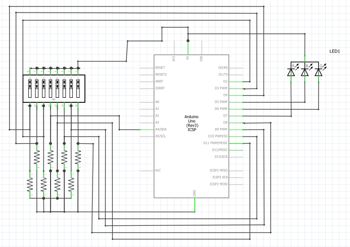
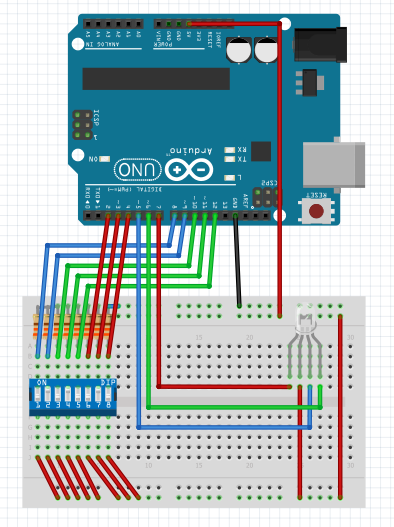
The Arduino's digital outputs were used to control the RGB LED. In order to change the intensity of each portion of the RGB LED, each individual color of the light was turned on and off for different amounts of a complete cycle. Essentially Pulse Width Modulation (PWM) was used to control the color.
To make the different levels of the colors, I simply changed how long each portion of the RGB LED was on. For example. If I wanted a teal (bluish-green) color I would turn the blue on half way and the green on half way.
A timing interrupt was used to control the RGB LED while the main loop of the code just read the DIP switch values. Instead of using digital read and write, I chose to read and write directly to the Arduino's port which is a bit quicker but more complicated if you aren't familiar micro controllers.
Thanks for checking out my project. Feel free leave comments and questions.


_ztBMuBhMHo.jpg?auto=compress%2Cformat&w=48&h=48&fit=fill&bg=ffffff)


_3u05Tpwasz.png?auto=compress%2Cformat&w=40&h=40&fit=fillmax&bg=fff&dpr=2)
Comments
Please log in or sign up to comment.