Qualcomm APQ8009 hardware Dev-Kit is executed for IoT/IoE product development reference. SmartSpeaker connects with service provider (GoogleNow, Cortana…) and transfers online information/concepts that come from customer. It plays songs via WiFi/Bluetooth and recognizes long-distance voice commands by mounting voice recognition engine. It also enables IoT device operation by voice, and transmits alarm messages with light or sound via WiFi and Bluetooth.
- Based on the hardware reference design from Qualcomm 410C, here’s the key parts list and component description.
From the hardware specification list, following system function block diagram is the first version of hardware design for reference. Although Qualcomm 410C post CPU with A9 processor and Inventec province Qualcomm APQ8009 for IoT/ IoE development kit since APQ8009 has 4x A7 processor, and should be strong enough for most applications, i.e. SmartSpeaker product.
Airplay and MultiroomThere are several way to implement Airplay & Multi-room audio playback support. The first clarify item what user define “Multi-Room”. In case End-user want Sonos-like functionality, the easiest way would be to integrate a Qualcomm AllPlay module. Consultants from Qualcomm are looking into posting AllPlay to Snapdragon APQ8009, and already released the detail information by middle of April 2016.
Far-field Korean keyword sporting can be supported by Qualcomm SVA. The requirement as support “Beamforming”. Currently APQ8009 could support 4 mics and Qualcomm’s Beamforming performs very well for far-field voice input with only 3 mics, in case user insist on 4 mics and Qualcomm could support 3rd party Beamforming algorithm through poring to APQ8009 QDSP6 via OpenDSP.
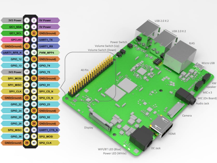
Hardware Board Overview:Avenger (APQ8009) enable camera with OV2718, audio codec with WCD9326 and USB, RJ45, and HDMI connection. Here’s the outcome overview for the connection, posts.
Start using hardware board, following the steps below:
- Step 1: Connect HDMI cable to HDMI connector with display monitor
- Step 2: Connect USB keyboard/ mouse with USB connector
- Step 3: Ensure the switches setup with ‘0011’, switch 3 (enable USB host mode, USB port and micro USB port)& 4 (enable HDMI) as ‘enable’ position
- Step 4: Connect power adapter to DC jack and press power key by 2 seconds to power up and power led will light up.
Please note that the first boot takes several minutes due to Android initialisation. Subsequent boot times should be faster.
Android ADB Command:Android ADB is a command line shell. It helps user communicate with Android devices easily. To install ADB driver, please follow Android developer webpage below.
https://developer.android.com/studio/run/oem-usb.html#InstallingDriver
PrerequisitesUse micro-USB cable to connect USB ports to PC host and ensure that the switch 3 of dip switches are set with ‘OFF’ position then PC host can communicate with Android devices through micro USB.
After Install Android ADB driver, Android ADB interface will appear in Device Manager.
Execute ‘command prompt’, and input command ‘adb shell’. Will find the prompt string ‘shell@msm8909’, that makes a successful driver installation.
During the process of development, system functions keep changing with target requirements. It needs to update system images to flash up Avenger functions.
- Qualcomm F/W image and Android image comprise overall Avenger images.
- Qualcomm F/W images – seldom changed.
- Android images – changed frequently.
- 1.1 Release Images download: There should be a site/server for images upload.
- 1.2 Extract images: Pick a preferable Windows directory to unzip your image file, an ‘Image’ directory is created, below is the images content list.
- 1.3 Flash Images: Pick up a preferable Windows directory to unzip image file, an ‘Image’ directory is created, below images content list.
Execute fastboot to flash images to onboard emmc storage, before getting started, make sure fastboot command directory is in PATH environment variable.
Following the steps to flash images:
- Plug in Avenger with PC.
- Open Device Manager.
- Confirm ‘
Android ADB Interface’ recognized correctly: Make sure ‘Android ADB Interface’ is recognized (‘Error! Reference source not found.’), otherwise, go through section step with ‘update Android ADB driver’.
- Open Windows ‘command prompt’ application.
- Change working directory to extracted ‘Image’ directory.
- Start ‘Burn_image.bat’ batch file.
Enter an item for your requirement to update images. To reboot flash images, enter ‘a’ for ‘adb reboot’.
Boot Configuration:There are 4 switch DipSwitch at the bottom side of the hardware board. For the normal operation with all switched setup as ‘off’ position.
- Switch 1, ‘USB BOOT’, when settings with ‘on’ position, the force boot over USB connection will from PC host. This’s only required by eMMC boot image upgrade.
- Switch 2, ‘SD BOOT’, when set to ‘on’ position, will force the SD to serve as the boot source for the hardware board when enable. You can use SD-card as the main boot source or it can serve as a method for eMMC boot image upgrade.
- Switch 3, ‘USB HOST’ switch hardware board to USB HOST mode. This switch is not part of the boot configuration.
- Switch 4, ‘HDMI SEL’ forces the DSI mix to route the MIPI-DSI to the DSI-HDMI Bridge. This switch is not part of the boot configuration.


Comments
Please log in or sign up to comment.