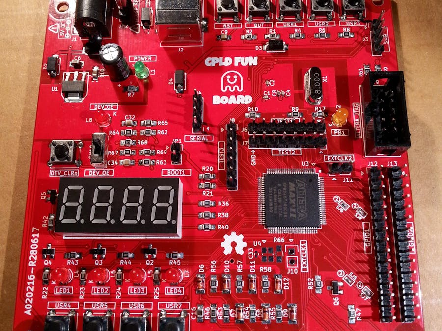
Two dev boards into one: an STM32-based Arduino and an Altera MAX II CPLD board to start playing with VHDL/Verilog, or just to try to use a CPLD with the Quartus II schematic editor. The cost should be about 5/6$ plus the PCB (I haven't done the precise BOM calculation yet...), buying the components "around". The "pluggable" LCD module and the optional stand-alone 50MHz oscillator aren't included in the cost count.
DetailsThe basic idea is to have a STM32 Arduino to use as "stimulus generator" for the CPLD (e.g. I2C master) and an Altera MAX II CPLD on the same board. In this way is easier to set up a complete "test bench" for the CPLD "application" (e.g. your custom I2C interface).
It is possible use an EPM570T100 too, "configuring" the PCB with eight solder jumpers (see the legend on the bottom side of the PCB, or the schematic).
The capacitors C31 and C35 are required only for the EPM570T100, so if you use an EPM240T100 do not populate them (as in the board shown in the photos, using an EPM240T100). Because currently I haven't any EPM570, when available I'll make an other board with it.
The CPLD Fun board in action:
The STM32F103 MCU is used as "stimulus generator" and as 8/36MHz clock generator for the CPLD, and is easily programmed using the friendly Arduino IDE through the USB connector.
Five push buttons (RST, BUT, USER1-USER3) and a led (PB1) are reserved to the MCU.
The STM32F103 MCU side is "Maple Mini" compatible, so it possible to use the STM32F103 Arduino core provided by http://www.stm32duino.com (more info here). For a short story about the Maple Mini and the stm32duino see here.
You need to flash the bootloader first using a cheap "St-Link V2" dongle through the SWD connector (or using a serial-USB adapter on the SERIAL connector. More info here).
To configure the CPLD (an EPM240T100C5 with 240 LEs, enough for some fun...) it is used the Quartus II IDE (free Web edition) and a cheap "USB Blaster" dongle through the JTAG connector.
A 4 digit 7-segment led display, four push buttons (USER4-USER7) and four leds (LED1-LED4) are reserved to the CPLD. There is also a connector for a common and cheap 1602A or 2014A LCD 5V module (that probably you already have got...).
On the CPLD side there are also a DEV_CLRn push button to clear all the internal FFs, and a DEV_OE switch to force all the CPLD pins in HiZ (to use these two functions you must explicit enable them first in the Quartus II IDE).
An optional on-board 50MHz oscillator is available too (not assembled in the previous photos), and there are also two connectors for external oscillators.
There are 22 I/O lines that "join" the STM32 and the CPLD, and on every of them there is a pin of three connectors (TEST1, TEST2 and TEST3). In this way it is possible "observe" signals exchanged between them with a scope or a LA. On this 22 I/O lines there are available various peripherals (e.g. serial, I2C, SPI) on the MCU side.
There are also others 25 GPIOs on the CPLD side (GPIO1 and GPIO2 connectors).
It is possible to make use for the Arduino STM32 or the CPLD as a stand-alone dev board, and use the TEST1-TEST3 connectors as normal GPIOs (holding the other chip pins in HiZ).
All this is shown in the following functional block diagram:
Typically to program this board you need to use together the Arduino IDE for the MCU and the Quartus II IDE for the CPLD.
Here is a typical session (using the Quartus II schematic editor for the CPLD):
Of course you need two USB on you PC/Workstation, one to connect the Arduino IDE to the MCU USB (the STM32F103C8T6 MCU has an integrated USB peripheral) and one to connect the Quartus II IDE to the USB Blaster dongle to upload the CPLD "configuration" using JTAG.
Here is a typical session layout:
- PCB_Layout_Guide.zip: PCB components assembling guides.
- A020216-R280617_Gerbers.zip: PCB Gerber files.
- A020216-R280617 SCH.pdf: CPLD Fun Board schematic.
More info and updates here.


Comments
Please log in or sign up to comment.