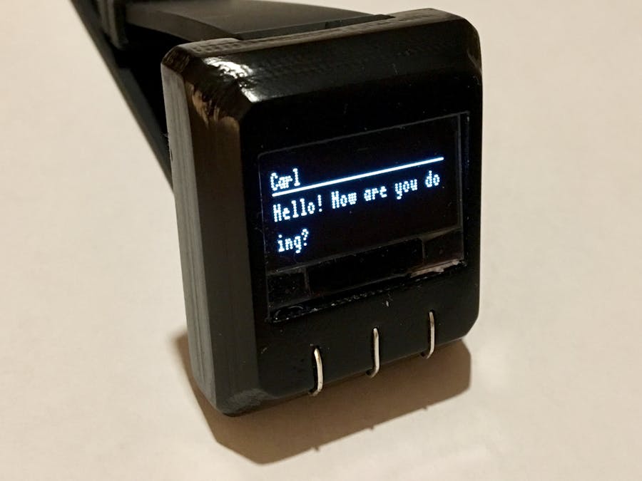
I wanted a smartwatch that showed me notifications from an iPhone, was small enough to wear, and had a rechargeable battery that lasted for at least a day. I created my own Apple watch based on an Arduino. It is a smartwatch based on an Arduino mini pro, which is connected to the iPhone over Bluetooth. The USB-micro port is connected to the battery which makes the charging easy and simple. The wires on the front are touch buttons which sense if you put your finger on them, which allows you to interface with the watch.
The watch will automatically synchronize the time with the time on the iPhone when a new notification is received. This makes the watch more reliable and less sensitive for delays in the Arduino. After 10 seconds, the screen will be turned off in purpose of saving battery. The screen wakes up if the middle button is touched or if a new notification is received.
I came across Luke Brendt’s page (http://lukeberndt.com/2014/ios-notifications-with-arduino/) and saw that he had created the same thing that I wanted to achieve, but I needed the device to be smaller and wearable. It is Brendt’s ANCS Arduino Library that I am using in this project. ANCS stands for Apple Notification Center Service which is described as following from Apple. “The purpose of the Apple Notification Center Service (ANCS) is to give Bluetooth accessories (that connect to iOS devices through a Bluetooth low-energy link) a simple and convenient way to access many kinds of notifications that are generated on iOS devices.”
Following is a tutorial in order for you to build this smartwatch on your own.
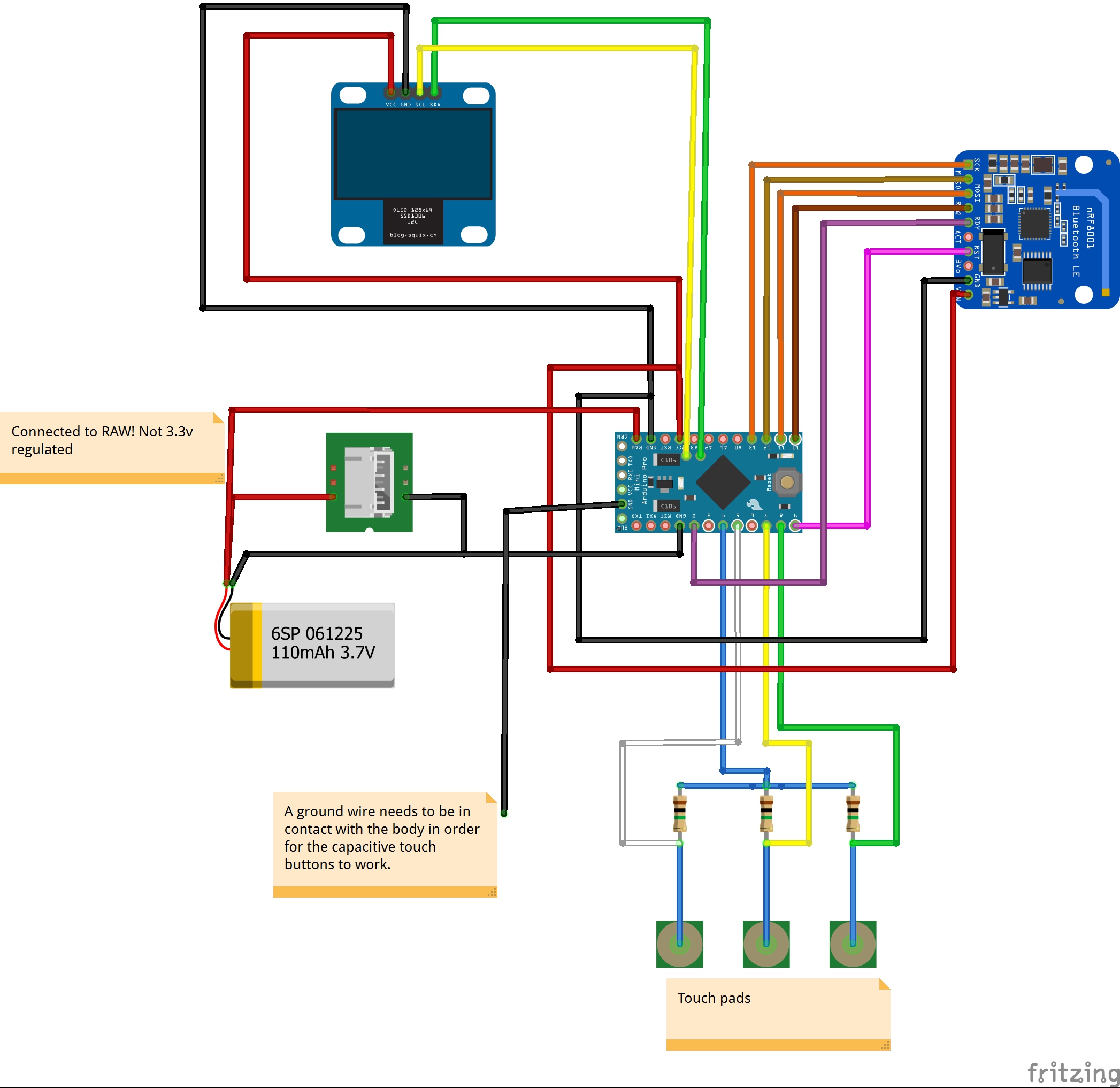
Step 1: Electrical hardware assemblyAs seen in the circuit diagram there are many wires to be connected, and all components should be close together which makes for a challenge.
After some iterations, I came up with these steps to make the assemble easier. I suggest looking at the pictures to see how I solved some problems with connecting wires.
1. Connect the Bluefruit LE to the Arduino with flexible wires.
2. Create the board for the touch buttons and attach the pins. Attach this board to the Arduino with flexible wires. (The pins are cut off from LED-diodes)
3. Modify some pins for the OLED display, and assemble it to the Arduino.
The following steps can wait until the code is uploaded and verification that the hardware functions properly has been done.
4. Connect a flexible wire to ground, make this long enough to reach the back of the watch, which needs to be in contact with the body. (This is needed because capacitive touch needs a ground reference to work properly)
5. Attach the micro USB connector with flexible wires to ground and RAW. Look at a USB micro pinout diagram to see how ground and positive voltage should be connected. (Note! Connect positive wire from USB to RAW and not VCC).
6. Attach the battery with flexible wires to ground and RAW (Note! Connect positive wire from battery to RAW and not VCC).
Also, it is necessary to customise a charger for the watch:
1. Cut a USB micro cable.
2. Attach red wire in USB cable to red wire from the battery connector, and black wire in USB cable to black wire from the battery connector.
IMPORTANT!
Note that the smartwatch CAN’T be charged directly with 5V from a USB with an ordinary USB micro cable. A Li-Po charger is needed instead, otherwise the battery can be damaged.
Comments:
Try to use tape to isolate between the components to avoid short circuit.
Step 2: SoftwareThe following libraries were used for the smartwatch. However, some needed a few modifications to work with the hardware used, which will be explained below.
Libraries:
- ANCS Library for Arduino (https://github.com/robotastic/ANCS-Library/tree/master)
- Bluetooth low energy SDK for Arduino (https://github.com/NordicSemiconductor/ble-sdk-Arduino)
- U8glib for the screen (https://github.com/olikraus/u8glib)
- Capacitive Sensing Library (https://playground.arduino.cc/Main/CapacitiveSensor?from=Main.CapSense)
The modifications made are the following:
1. Library: ANCS Library for Arduino, File: notif.cpp, Row: 826. This needs to be changed in order for the Bluefruit module to work.
aci_state.aci_pins.reset_pin = 9; // This was changed to 9
In order for the time to synchronize properly following changes need to be implemented to fix some bugs in the library
2. Library: ANCS Library for Arduino, File: ancs_data_source.cpp
- Replace the entire code with the code from the ancs_data_source.cpp PDF at this link
- Add the following row commented below in ancs_data_source.cpp at row 217.
case  ANCS_NOTIFICATION_ATTRIBUTE_DATE:
        debug_print(F(", Date: "));
	// YYYYMMDDTHHMM
	datetime = (char*)malloc(5); //Add this row!
	strncpy(datetime, buffer, 4);
3. Library: ANCS Library for Arduino, File ancs_notification.h
- Replace the entire code with the code from the ancs_notification.h PDF at this link.
The Arduino mini pro is missing an on-board programmer, an external is therefore needed. I used this one: Sparkfun FTDI (https://www.sparkfun.com/products/9873).
Comments:
The attached zip-folder contains the code running on the Arduino, and all libraries needed. The libraries are modified as above. The Arduino code is commented which hopefully will explain the functions.
I encountered a problem while trying to compile the code with Arduino IDE 1.8.3, this due to a known error in the GCC compiler. I downloaded and installed Arduino IDE 1.0.6, and was able to compile and upload the code.
Step 3: Case for the SmartwatchDraw a case that is large enough to hold all the components, attached in the zip-folder is the stl-file for the case used in this project. (Two iterations of the case design were made. That is why the shape of the case may vary in some of the pictures.)
The back cover is made from an aluminium sheet from an old box. Cut out a piece that fits on the case and drill holes for the screws. For the case and the wrist band used in the project a gap between the holes is needed. It is good if the back cover is from a material that is electrically conductive, since the ground-to-body wire will be connected to this back cover. To get clean and straight edges on the aluminium sheet I hold the sheet between two wooden pieces, and used a metal saw.
The 3D-printed case needed some treatment, these steps were done:
1. Grind the case with a fine sandpaper.
2. Apply filler from a spray can, make sure it covers the case well.
3. Grind the case with a fine sandpaper again. (Step 3 and 4 may need to be repeated until a smooth finish is reached. I repeated these steps three times.)
4. Apply paint from a spray can, make sure it covers the case well.
Comments:
Follow the instructions on the spray cans in order to achieve best results.
Step 4: Final assemblyFirstly, insert the touch button pins through the lower holes in the case. Bend them back and insert them in the top holes in the case. Press the wires down to make them fit good and smooth.
Just push down the rest of the components, try to get the screen in a good location. I had a severe problem to align the screen in the case. This depends both on the component-assembly and also the case design. It is the reason why the screen is a bit rotated.
Push the USB micro connector through the hole in the side. (I used tape to get at thigh fit in the hole, to allow the connector to stay in place.)
Solder the body-to-ground wire to the back cover, and isolate the back cover with tape. Attach the back cover with four screws.
Step 5: How to use the SmartwatchThe smartwatch is simple to use. Just go in to Bluetooth settings on the iPhone, enable Bluetooth, and look for a device called “ANSC rusk” chose this and select pair. The smartwatch and the iPhone is now paired and the smartwatch will receive the same notifications that appears on the iPhone.
The Watch will be restarted if the middle button and the right button are touched at the same time. This is useful if a problem with the connection occurs.
To charge the battery just plug in the modified USB cable and connect it to the Li-Po charger.


_3u05Tpwasz.png?auto=compress%2Cformat&w=40&h=40&fit=fillmax&bg=fff&dpr=2)
Comments
Please log in or sign up to comment.