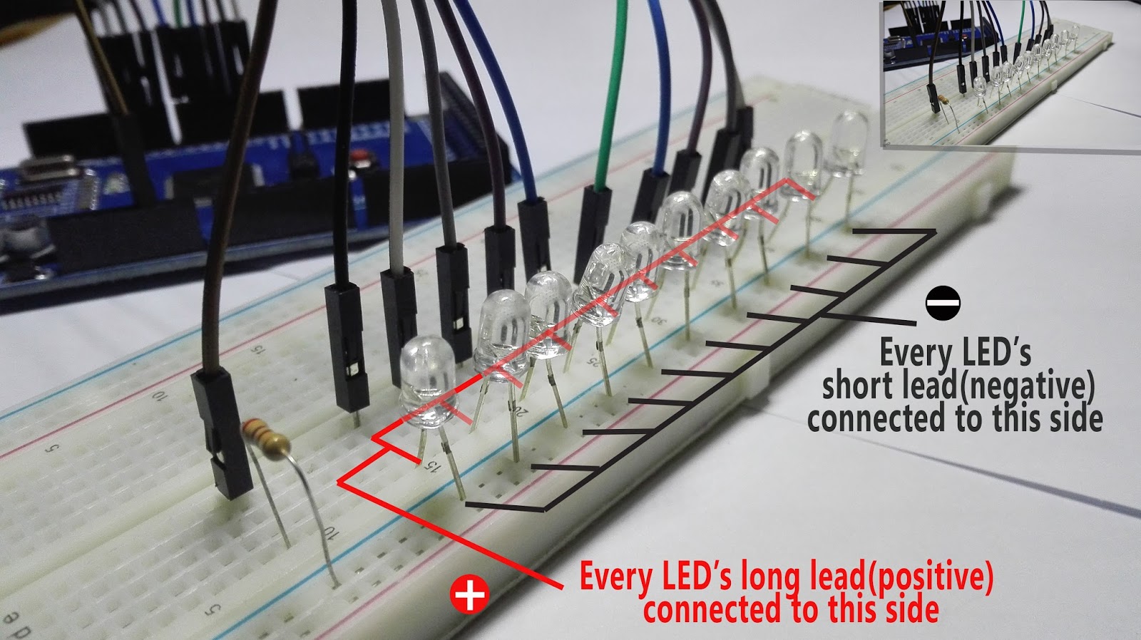
Male to male jumper wires are connected to each positive leads of LEDs and the other ends are connected to the Arduino Mega micro controller's digital pins according to a order given in the picture
Digital pins 2 - 11 of Arduino MEGA board used. Ground is connected to bread board through a 270 Ohm resistor. This resister controls required voltage and the current to LEDs.
Now circuit is ready. We have to implement the codeThe Mega 2560 board can be programmed with the Arduino Software(IDE).
This code will make the LEDs blink in a sequence, using only pinMode(pinNumber, output/input), digitalWrite(pinNumber, 0/1) and delay (time in milliseconds) functions.
We can use a pin as a input or output. pinMode() is used to define how we are going to use a pin.So we use it as pinMode(pinNumber, OUTPUT/INPUT).There are digital pins and analog pins in Arduino Mega board.So we have to define what type of pins are going to used. To define that we can use digitalWrite() or analogWrite() functions.
And also we can assign value of output of the considered pin using digitalWrite() or analogWrite() functions. We use delay() function to pause execution of the code between desired time period.
Brief introduction of the codesetup() functionThe setup() function is called when the code starts. Use it to initialize variables, pin modes, start using libraries, etc. The setup function will only run once, after each power up or reset of the Arduino board.
loop() functionAfter creating a setup() function, which initializes and sets the initial values, the loop() function does precisely what its name suggests, and loops consecutively, allowing your program to change and respond. Use it to actively control the Arduino board.
Steps to upload your sketch- Connect your Arduino using the USB cable
- Choose Tools→Board→Arduino / Genuino Mega or Mega 2560 to find your board in the Arduino menu
- Choose the correct serial port for your board
- Click the Upload button
A few seconds after the upload finishes, you should see the amber (yellow) LED on the board start to blink. After uploading the code successfully, you can see the knight rider circuit running.


_wzec989qrF.jpg?auto=compress%2Cformat&w=48&h=48&fit=fill&bg=ffffff)


Comments
Please log in or sign up to comment.