ABOUT THIS PROJECT
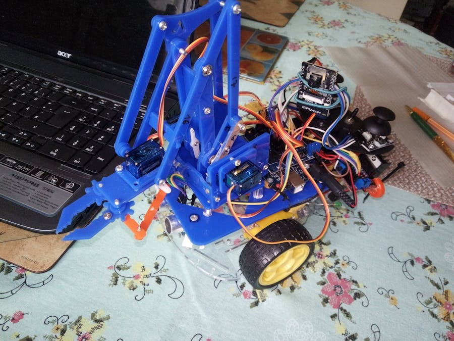
Robotic arms are now used in a wide variety of applications, from industrial automation to automatic burger making arms. The key component of any automatic robotic arm is its ability to learn motions or the ability of arms to be programmable by the user. The ARA (Arduino Robotic Arm) is an initial project, a first phase, of one of the most popular project carried out by the Arduino community. Now You can at Home built the Robot Arm on 2WD Arduino car Kit.
A video with RobDino in action can be found here:
In this tutorial we will learn how to make an Arduino Robot Arm which can be wirelessly controlled and programmed using a custom-build Android application. But spatial orientation is also possible with a camera. Using the button in the app we can manually control the movement of each servo or axis of the robot arm. Also using the “Save” button we can record each position or step and then the robot arm can automatically run and repeat these steps.
The purpose of this intractable is to develop step by step a project for controlling and programming of a Robot Arm, simulating the basic functions of an moveable robot. It also has tutorial videos for programming and calibrating, and wrote a detailed assembly manual. In the following article we took another step and equipped Robot Arm with the Camera, initially only as an option, but soon as a finished solution.
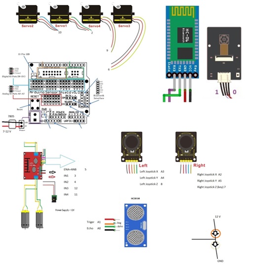
Getting Started: Arduino Robot Arm 4DOF Mechanical Claw KitBy using a ready chassis it is possible quickly build a working model. If you buy "Robot Smart Car Kit" and MeARM or Arduino Compatible Robotic Arm Kit, that includes a chassis, wheels, motors and other mechanical components, to build the robot, we will need possible only few additional electronics to control the motors and sensors to detect position. The whole electronic design was made based on the Arduino Uno.
• The project can be used to control robots with 4 DOF ( "Degrees of Freedom").
• The robot can be controlled in "LOCAL" and "REMOTE" modes (the last one via an Android device)
• During the program phase, user can change the control mode from "LOCAL" to "REMOTE" and vice and versa.
• Information to user will be provided thru LED
At the end we add batteries and charger to power supply the robot and it will be ready for using.
For powering the servos we need 5V, but this must come from an external power source because the Arduino is not able to handle the amount of current that all of them can draw. The power source must be able to handle at least 2A of current. So once we have connected everything together we can move on to programming the Arduino and make the Android app.
The controller uses two joysticks for collecting human inputs.
The MeArm is among the most popular Arduino robot arms around, and for good reason. Typical Arduino robot arms — and robot arms in general — are rated in terms of degrees of freedom (DOF). This refers to the number of rotational joints contained within the design of the robot. This terminology is specific to robot arms, but also interchangeable with the more typical “axes“. For example, a 4DOF (4 Axis) robot arm will have four discrete axes of motion. Not all of these axes have to be powered, for instance the MeArm (see below) has a “self adjusting” gripper designed to always be parallel to the arm’s base.
Another factor to look out for is payload — how much an arm can lift. This is determined by the number and types of motors within the arm — usually some sort of servo or stepper motor — as well as the design of the arm.
The robotic arm comes flat packed for assembly and requires very little soldering to get up and running. Integrates 4 SG90 servos that allow 4 degrees of movement and can pick up light objects with the claw. Let's begin!
Robotic Arms can be classified according to the number of "joints" or "Degrees Of Freedom" (DOF) they have.
• The "Base", or "Waist", usually can turn the arm 180o or 360o, depending of the Servo type used (here in this project, a 180o Servo was used)
• The "Shoulder", is the responsible for "raising or lowering" the arm vertically
• The "Elbow" will make the arm "go forward or backward".
• The "Claw" or "Gripper" works by opening or closing to "grab things."
• If the servos have problems and vibrate a lot, make adjustments at the "delays" of your code.
We start assembling the robot arm from the base as shown in the picture.
By using a ready chassis it is possible quickly build a working model. If you buy "Robot Smart Car Kit" that includes a chassis, wheels, motors and other mechanical components, to build the robot, we will need only few additional electronics to control the motors and sensors to detect position.
In order to complete the assembly we just have to connect the upper and lower parts frames using some bolts and brackets, and then connect the electronic components with the control box using the provided cables.
Finally I attached the gripper mechanism onto the last servo and the Arduino robot arm was completed.
There are many descriptions of assembly hardware so it will be given more software detail.
APPS AND ONLINE SERVICES:
For the Bluetooth network, the HC-06 or HC-08 will be used. In the first version, ESP was only used for the image. Optionally, ESP32 can also be used as a control. Next, we are going to introduce the use method for HC-06 Bluetooth module.
In store there are a lot of different apps for controlling Robot Arm. It's about the same principle. However, the difference is in the graphic design. To easily use the HC-06 Bluetooth module to control the robot arm, we particularly use the APP control - shown below.
You can download the APP for Bluetooth from the link:
https://drive.google.com/open?id=10U7EWyCyb5bGUxWm3DXRXGKEm1UQGU4Q
In the simplest App there are 10 control keys. When connect well the HC-06 Bluetooth module to Android phone using our APP, press the control key, Android phone will send and receive a corresponding value.
A slightly better version can be found on APP Store. Search “keyes arm”,but” then the code needs to be modified.
However, if ESP32 camera module is used instead of Bluetooth, then appropriate programs for ESP32 must be prepared and uploaded to Camera Module.
Learn more about remote control and video surveillance with ESP32 for miniCar and RobotArm on the page: https://www.hackster.io/Kenan-Paralija/remote-control-and-video-monitoring-with-esp32-for-robot-66332b
Arduino Robot Arm CodeThe project is not complicated, but it has many variables. The most prudent is to clearly define them and let his remarks on a unique file:
As the code is a bit longer, for better understanding, I will post the source code of the program in sections with description for each section. And at the end of this article I will post the complete source code.
So first we need to include the Software Serial library for the serial communication of the Bluetooth module as well as the servo library. Both of these libraries are included with the Arduino IDE so you don’t have to install them externally. Then we need to define the six servos, the HC-06 Bluetooth module and some variables for storing the current and previous position of the servos, as well as arrays for storing the positions or the steps for the automatic mode.
Code Description:
Main loop controls reads command from Bluetooth or Wireless module ESP32. As shown in the following listing, after each command received from the app, other subroutines for miniCar are executed. (Actions from the above table are then carried out).
The standard Arduino library "Servo.h" was developed for analog servos. It is important that the servos have time to get to a certain point before receiving a new command. In the case of the RoborArm, by changing the appropriate variables is controlled a servo.
For example if Bx1H==HIGH, then servo for "Shoulder" upper arm is moved. As can be seen in the following listing, changing variables has the same effect as touching the joystick.
The only difference is that harder touch of joystick can make faster movement of servo. This achieves precise control of movement with remote control.
For ”recording" the sets of coordinates (or steps) that the robot should play, I will use data arrays:
Note that I'm not keeping the "stored" position and at the end of the "robot" program, the index is back to zero and the robot will wait for the recording of a new sequence (the program is lost). Alternatively, you could keep these data arrays in the Arduino EEPROM, for example. Doing that, the program would be executed again or even you could have more than one stored program.
Everything else is done as is easy to find on the internet.
COMPONENTS AND SUPPLIES
Parts needed in this project:
2WD Robot Smart Car Kit
Arduino uno, if not keep in kit
MeARM or Arduino Compatible Robotic Arm Kit
BTS7960B Motor Driver (H-Bridge)
HC-06 or HC-08 bluetooth module, optional Camera ESP32
SRF05 Ultrasonic Sensor
Micro Servo x 4
Batteries: 7.4V 800mAh or 11.1V 1300 mAh
Jumper and cables
Nuts and bolts (M2, M3)
Conclusiones
The connection between Arduino and ROS (Robot Operating System) for real applications is very interesting and opens the possibility to explore the rigorous software development in ROS. Up to this article, we have controlled the robot in the common state for teleoperation, but the real essence of robotic arm control lies in utilizing the kinematics and dynamics of the system.
„Der Ingenieur war und ist ein Geschichtsschreiber. “ (The engineer was and is a historian.) -James Kip Finch
As always, I hope this project can help others navigate the exciting world of electronics, robotics, and IoT!
Weitere Projekte finden Sie unter:
Simple Follow-Me Function for 4WD Arduino car Kit
https://www.youtube.com/watch?v=SFOdn3Z2GS0
use the GY-521 module (MPU-6050 Board) to make a 2WD robotcar drive in a straighthttps://www.hackster.io/Kenan-Paralija/making-a-2wd-arduino-vehicle-drive-straight-ae40ee


Comments
Please log in or sign up to comment.