


Hardware components | ||||||
_ztBMuBhMHo.jpg?auto=compress%2Cformat&w=48&h=48&fit=fill&bg=ffffff) |
| × | 1 | |||
 |
| × | 1 | |||
Where ever you go, you are surrounded by LED matrix displays. Using driver chips like MAX7219 (since 1983) and SPI libraries, operating them has become very easy. This is to understand how it can be done without. That is why we did not use this one:
but a naked one instead:
Actually, it offers 7 x 5 LEDs but we used only 5 x 5. To enable even handicapped students, some 2mm sockets were mounted. This is a view from the bottom:
The same accounts for the ARDUINO:
So students could easily connect both parts together:
The task was to display some patterns:
The first steps were to activate single LEDs by writing HIGH and LOW to certain pins. But at the end we wanted some animations. So this was the result:
// TW20-11EWA
// 7 rows with 5 LEDs each
// but only 5 x 5 are used
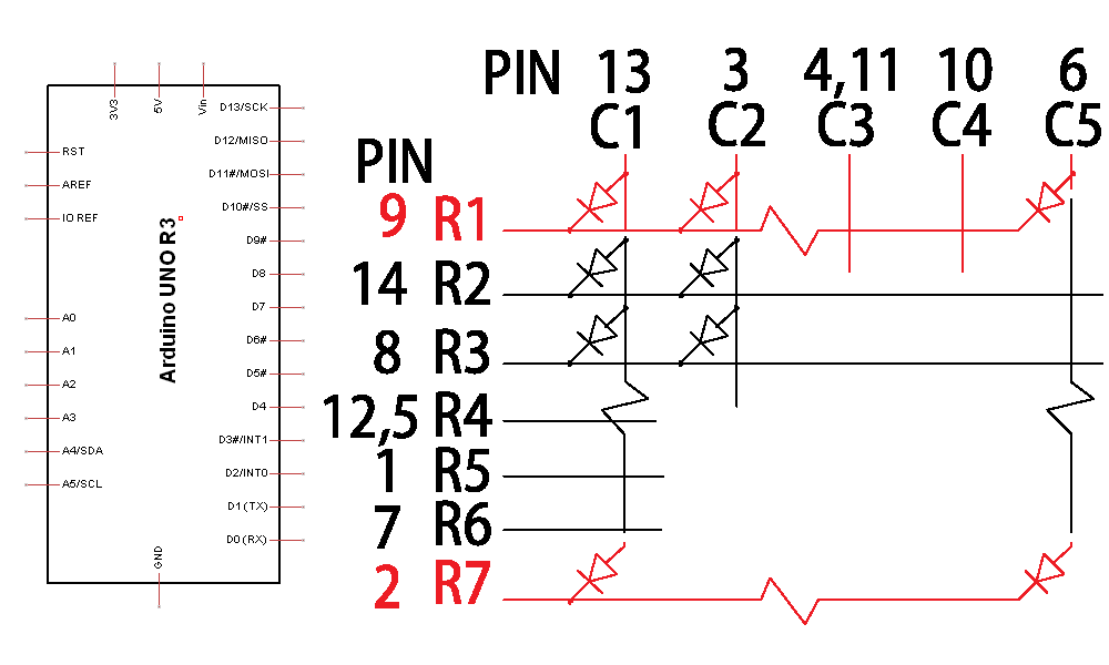
// Cathodes:
byte row[] = { 5, 6, 7, 8, 9};
// Anodes:
byte col[] = { 10, 11, 12, 13, A5};
/*
For some reason, pins d0 to d4
could not be used here.
A4 is used to indicate ISR is
active to be watched by a scope.
*/
const byte sr = sizeof row;
const byte sc = sizeof col;
int dt1 = 6; // avoid flickering
int dt2 = 150;
byte tc = A4; // CPU time check
volatile boolean M[sr][sc];
void setup() {
Serial.begin(9600);
Serial.println(__FILE__);
pinMode(tc, OUTPUT);
// activate the 2nd ISR routine:
TIMSK0 = 3; // OVERFLOW + COMPA
}
int x, y;
void drawLine(int xDir, int yDir) {
for (int i = 0; i < 4; i++) {
M[x][y] = true;
delay(dt2);
M[x][y] = false;
x = x + xDir;
y = y + yDir;
}
}
void clear() {
delay(dt2);
for (int i = 0; i < sc; i++)
for (int j = 0; j < sr; j++) M[i][j] = false;
}
void loop() {
for (int i = 0; i < 5; i++) {
drawLine(1, 0); // x+
drawLine(0, 1); // y+
drawLine(-1, 0); // x-
drawLine(0, -1); // y-
}
for (int j = 0; j < 5; j++) {
// diagonal:
for (int i = 0; i < sc; i++) M[i][i] = true;
clear();
// horizontal:
for (int i = 0; i < sc; i++) M[2][i] = true;
clear();
// diagonal:
for (int i = 0; i < sc; i++) M[i][sc - i - 1] = true;
clear();
// vertical:
for (int i = 0; i < sc; i++) M[i][2] = true;
clear();
}
}
ISR(TIMER0_COMPA_vect) {
// called once a millisecond
digitalWrite(tc, HIGH);
static byte i = 0;
static byte j = 0;
// switch off current LED:
pinMode(row[i], INPUT);
pinMode(col[j], INPUT);
// check the whole M
// until you found a "true":
for (byte k = 0; k < sr * sc; k++) {
if (++j >= sc) {
j = 0;
if (++i >= sr)
i = 0;
}
// if required, this LED on:
if (M[i][j]) {
pinMode(row[i], OUTPUT);
pinMode(col[j], OUTPUT);
digitalWrite(row[i], LOW);
digitalWrite(col[j], HIGH);
break; // and exit
}
}
digitalWrite(tc, LOW);
/*
ISR takes 100 microseconds that
is 10 per cent of the CPU time.
*/
}Please note that we did not use one of the free Timers #1 and #2, but enabled an additional interrupt procedure that becomes executed at the same frequency as the TIMER0_OVERFLOW_vect which ist providing millis() and delay().


Comments
Please log in or sign up to comment.