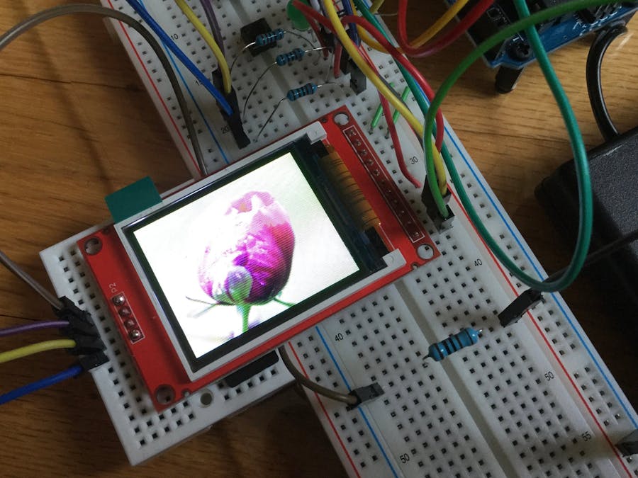
This started off as a Halloween costume prop; I wanted a TOS tricorder. The tricorder screen was almost a perfect match for a 1.8" TFT, so I bought one. It was not functional, so I returned it and got the DSD Tech model (with a yellow header with 11 pins and 4 connectors for the SD card.
I tried the Adafruit ST7735 driver, but could not get it to read the BMPs from the SD card reader. I switched to the Arduino TFT driver, but it was very slow and would stop working after loading several BMPs. Someone in the forum (David Prentice??) helped me by encouraging me to go back to the Adafruit driver.
After much research and plenty of mistakes, I got my tricorder simulator to work! I did not want others to go through the same hassles I did, so I wanted to post a very simple sketch that will:
1) initialize the display;
2) initialize the card reader;
3) load a BMP from the card reader; and
4) display the BMP on the screen.
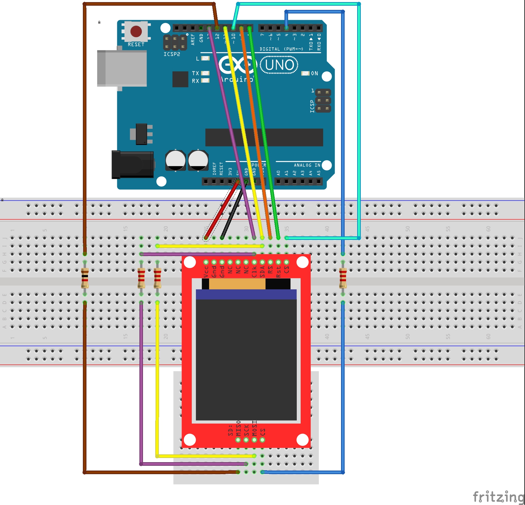
In the Arduino TFT tutorial, I read that you needed to use hardware SPI to get both the screen and the card reader to work simultaneously. That is what I have done. However, I saw so many instances where people switched pins 9DC and 8RST that I decided to try that. Both seemed to work, so I ran a sketch using both configurations that cycled through about 24 BMPs. The average for the Arduino-recommended configuration (9DC and 8RST) was 25 milliseconds shorter that the average for the switched configuration (9RST and 8DC) that so many people were using. The diagram is below:
I hope everything is correct! (This is my first Fritzing!)
The DSD Tech 1.8 TFT screen with SD has slightly odd pin labels:
- RS seems less common than DC;
- CLK seems less common than SCK; and
- SDA seems less common than MOSI.
The code is in the "Software" section. Nowhere could I find documentation on the line:
SdFat SD;
I cannot say what that does. I am a newbie leading newbies.
The BMP I used (which must be in the root directory of the SD card) is here:
I have a short video, but I do not know how to embed it here.


_ztBMuBhMHo.jpg?auto=compress%2Cformat&w=48&h=48&fit=fill&bg=ffffff)


Comments
Please log in or sign up to comment.