


Software apps and online services | ||||||
 |
| |||||
Hand tools and fabrication machines | ||||||
 |
| |||||
 |
| |||||
| ||||||
I started working on this project during the summer vacantion of the previous year, after I have done some brainstorming for a cool PCB project and came up with the idea of building something which squeezes as much as possible out of an 8-bit microcontroller. Since then, TinyCADE went through 4 iterations, from an ATtiny85 and a 0.96" OLED on a perfboard powered by AAA batteries to a late prototype, ready for production!
It all started with an ATtiny85 (upper-left) connected to a CD4021 shift register (right) for reading the buttons' state, a small SSD1306 OLED screen and a 47C16 2Kb SRAM IC (middle-left) for storing the framebuffer.
I'd like to mention that TinyCADE would not have existed today without the support of JLCPCB, who sponsored the manufacturing process of the PCBs. You can order high-quality PCBs from https://jlcpcb.com/RAT
DetailsTinyCADE is a small handheld game console having the AVR128DB64 microcontroller at its heart. The device is intended to be used by, but not limited to retro gaming enthusiasts, programmers, students, makers, pretty much everyone who enjoys playing and sharing games inspired by the 8-bit era.
As a small "companion", I have also made a breadboard extension board which breaks out the debug and unused GPIO pins of the microcontrollers and the power supply rails, essentially turning the TinyCADE into an Arduino-compatible development board and helping with unbricking it in case of an unfortunate event :)
- AVR128DB64 8-bit microcontroller running at 24Mhz (overclockable up to 32Mhz using the internal oscillator). It has 16Kb SRAM, 128Kb flash and 0.5Kb of EEPROM. This is the main microcontroller, which the games will run on.
- A chiptune synthesizer having the sound generation part fully written in AVR assembly, running on an ATtiny1614 microcontroller at 20Mhz. In this configuration it can mix up to 8 channels with individual amplitude and waveform (square, triangle, sawtooth, noise, PCM) at 44.1Khz, as well as apply effects such as ADSR envelope, vibrato, arpeggio and slide at 100hz, making use of every single available clock cycle. The audio signal is fed into a small class D audio amplifier, through the DAC pin. The main microcontroller communicates with the synth via USART.
- 1.6 inch 128x64, 4 bits per pixel grayscale OLED
- 8 tactile buttons + 2 side buttons (power and reset)
- RGB LED because why not
- 600mAh Li-Po battery charged via the MCP73831 IC from Microchip
- Power management and time keeping via the ATtiny212 microcontroller. It receives commands and sends battery data to the AVR128DB64 via UART.
- 1.5W speaker
- MicroSD card support (SDHC), allowing to load different flash files onto the AVR128DB64 without the need of a computer or any external device.
- USB Type-C port for charging the battery and communicating with the main MCU via the FT232RL IC
- Arduino IDE compatibility, many thanks to DxCore by SpenceKonde (https://github.com/SpenceKonde/DxCore)
Here is a small demo I've made for fun in order to test the chiptune synthesizer. It showcases the previous iteration of TinyCADE hooked up to a 4 Ohm speaker, playing a portion of the "Dancing Polish Cow" meme song. The Arduino UNO board serves as a "jtag2updi" interface for flashing the ATtiny1614.
The song is stored as a MIDI file on the PC and is sent to the device through USB, using a sketch written in Processing. Enjoy it!
Check out the project's Instagram page for more cool stuff: https://www.instagram.com/tinycade_official
To be honest, the previous TinyCADE PCB was not too good: the extension board was attached via a standard 40 contacts, 1.27mm pitch pin header which wore out after a few dozen cycles and was quite unreliable, a humming sound was constantly present in the speaker (as a bonus, the brighter the OLED, the louder the sound), the ATtiny212 microcontroller (responsible for power management and timekeeping) would hang unexpectedly when communicating with the AVR128DB64 via I2C (details at the end of the log) and the component layout was quite messy. I really hated it.
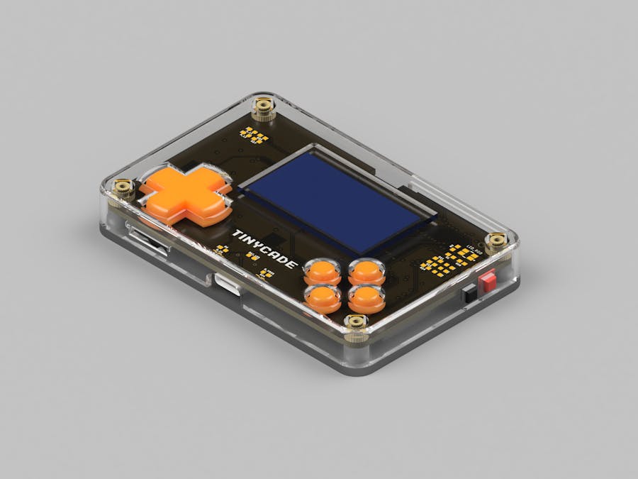
I received the PCBs for the latest TinyCADE iteration for free about 2 months ago, from JLCPCB through their Student Sponsorship Program and after a lot of soldering, it looked like I managed to fix all of the problems mentioned above. I decided to celebrate by offering TinyCADE a 3D-printed, spray-painted enclosure and buttons (the same model as in the renders) using PLA (that's what I've had at the moment).
Also, I have been working on an Arduino library for TinyCADE. Check out the GitHub link on the project page. I will also publish the power management microcontroller and synth source code when the project is finished.
After redesigning the whole PCB using better practices, all the speaker humming was gone. Only a faint white noise can be heard by sticking my ear onto the speaker. Also, I modified the BOM to have IC's with better availability because of the global chip shortage.
Also, I replaced the Extension Backpack connectors with these bad boys from Harwin: the M55-6104042R and M55-7104042R. Here is how the real TinyCADE looks, apart from the renders:
This tiny, but mighty microcontroller with just 128 bytes of SRAM, 2Kb of flash and 64 bytes of EEPROM acts as a power manager. When TinyCADE is turned off it enters power down mode, bringing the total current consumption down to a few μA. Only the PIT interrupt of the internal RTC fires up every 1 second for incrementing a 32-bit integer which acts like a timestamp.
When the power button is pressed, a pin change interrupt is fired and the 5V boost converter is enabled, having the role of the main power supply of the device (PAM2401 IC), powering the 3.3V regulator and the +14V boost converter for driving the OLED. During the time when TinyCADE is on, it "listens" for commands formerly received via I2C, monitors the battery voltage and if it falls below a hardcoded threshold, the the 5V boost converter is disabled and the ATtiny enters power down mode to help protect the battery, which also has a PCM including over-discharge protection.
The I2C problemIn the previous iteration, the ATtiny212 was acting as a slave, while having the AVR128DB64 as a master on the I2C bus. The problem is that the master power supply was dependent to the 5V boost converter, while the slave was always powered up from the LiPo battery. Also, 10k resistors were used on the SDA and SCL pins for pulling the lines up to 3.3V, which had the same problem. This led to more checks to be done, while also increasing the already large I2C implementation footprint on the small 2Kb flash memory of the ATtiny.
Also, the AVR128DB64 had to keep polling the ATtiny to check if the device is about to shutdown, causing overhead to the main application.
In the current version, the ATtiny212 communicates with the AVR128DB64 via USART, using a simple logic level conversion circuit for not destroying the main microcontroller pin with ~4.2V on high state, when the battery is fully charged.
This way, the protocol implementation is much more straightforward, reducing its flash footprint to about 300 bytes of compiled AVR Assembly (including peripheral initialization, interrupts and read/write routines with rx/tx buffers).
Moreover, since the transmitting and receiving pins are now separate, the AVR128DB64 no longer needs to poll the ATtiny212 for incoming device shutdown, so I feel like I've made a good decision to replace I2C with USART for this application.
I am aiming to have main microcontroller notified approx. 500ms prior to shutdown in order to have enough time to properly turn off the OLED and cancel any ongoing operation, for example writing a file to the inserted SD card.


Comments
Please log in or sign up to comment.