


Hardware components | ||||||
| × | 1 | ||||
| × | 1 | ||||
| × | 1 | ||||
| × | 1 | ||||
| × | 1 | ||||
 |
| × | 1 | |||
| × | 1 | ||||
| × | 1 | ||||
| × | 1 | ||||
 |
| × | 1 | |||
| × | 1 | ||||
| × | 1 | ||||
 |
| × | 1 | |||
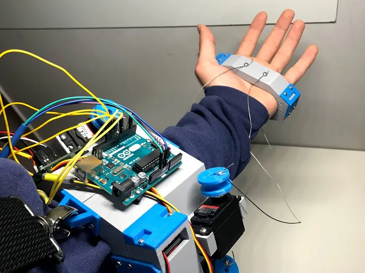
The purpose of Gen 2 is to help move a patient's wrist that has been damaged from an accident by pulling their hand inward and outward. Originally, the Gen 2 was created for AT&T 2017 Developer Summit competition, then I decided to make it open source for people to build, modify and improve the project. Furthermore, this project is not at the level of practicality because most of the parts have been reused from Gen 1 robotic hand. Also, this is the second version where the design is much simpler to 3D print.
Cost:The cost for this project depends on where you purchase the items and the shipping cost. I spent $30 on this project. it's important to note that 80% of the items were reused from Gen 1 robotic hand.
IMPORTANT NOTE:
Please email, message or comment if you have any questions: leoboghozian@gmail.com
Please check to make sure the arm brace will fit on your arm. You may need to modify the design to fit your arm.
Measure your wrist at three places-2 inches (50.8mm) apart and then use those numbers to modify the design.
Refer to the CAD folder and modify the design to fit your arm.
If you’re using Fusion 360, open the CAD file, Brace Walls > Sketches > Change the Inner Diameter for Sketch 1 through Sketch 3. (Using the measurements you got)
Step 1: MaterialsMaterials: I have divided the materials into two categories “Important” and “Optional”. “Important” materials are crucial to have in order to complete the project. “Optional” materials are extra tools that can aid you during the process. Also, you will need an access to a 3D printer in order to print the parts.
You may wish to purchase or use different equipment (Screws, sensors, etc.) from what is listed below as long as the dimensions are identical. If the dimensions differ, you will need to modify the design.
You will need a shoulder strap in order to keep the device into its place. I used a shoulder strap from a messenger bag.
The servo motors have been modified to become continuous rotational servos or motors. Refer to this link below in order to modify your servos. (Be very cautious, because you can easily mess up the positioning).
The first prototype I used the “Braided Stealth Superline” wire, then I switched to the “Coated Stainless Steel Wire”, however both options work but the stainless steel wire is more suitable for the project.
Important:
- Long Cross Screwdriver
- Soldering Iron + Solder
- Drill
- 6 x AA Battery
- 9V PP3 Size Battery
Optional:
- Breadboard
Note: All the screw holes are undersized to make sure the 3D Printer does not print oversize the holes where the screws will fail to hold the parts together.
I have given a bulky design to the brace with the idea in mind to make it easier to 3D print and easy to work with, therefore I focused on a hexagonal design. Also. there are some empty spaces enabling you to add further modifications.
- 1,2, 3 and 4: The “chassis” of the main project.
- Front_Locks: Front locks that will hold the brace together.
- Rear_Locks: Rear locks that will hold the brace together.
- Big_Battery: Holds the 6 x AA Batteries.
- Big_Battery_Lid: The lid that will be attached to the “Big_Battery” to hold the batteries in place.
- Small_Battery_Holder: Holds the 9V PP3 Size Battery.
- Small_Battery_Lid_Front and Back: The lid that will be attached to the “Small_Battery” front and back.
- Small_Battery_Lock: Locks the small battery on the brace.
- Hand_Brace: Wraps around your hand in order to get a nice grip.
- Servo Horn: These are created in order to wrap the wire around the servo without tanglement. However, it needs improvement!
- Identification (Optional): You can edit the CAD design in order to write your own name on it.
The Button Switch Setup includes: Buttons, (1k) resistors, jumper wires.
Refer to this link if you want to understand how the Arduino Button Switch functions: https://www.arduino.cc/en/tutorial/switch
Gen 2 Complete Electronic Setup includes: Buttons, (1k) resistors, AA batteries, 9V PP3 battery, four modified servos, and jumper wires.
The 9V PP3 battery will be powering the Arduino UNO separately, therefore attach the connector to the battery and make sure it fits into the external power supply port. The 6xAA battery will be powering the motors.
Step 4: Preparing the Parts for AssemblyNow that we have 3D printed the necessary files, we need to make sure the screws can fit perfectly. We will use a sanding tool, knife or an Xacto knife to remove the excess that we don’t need. Also, we need to make sure that the four servos fit into the proper areas perfectly with no problem. You may need to use the drill in order to increase the diameters of the holes to make sure the screws fit nicely and also to have a good grip. Use a sanding tool in order to make the surfaces smooth/flat for better assembly fit. Use a knife or an Xacto to remove the excess fillmanet.
Step 5: Wire OrganizationI actually didn't organize my wires completely, I simply used tape and tubes to organize the servo wires from the button wires. Therefore, it’s up to you how you want to organize your wires. If you wish to fully organize the wires, you can simply use tubing and electrical tape. Also, you can modify the design to add extra features that can assist you with wire organization
Step 6: AssembleUpload Gen 2 Code


Comments
Please log in or sign up to comment.