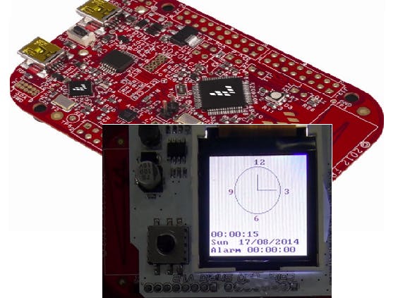
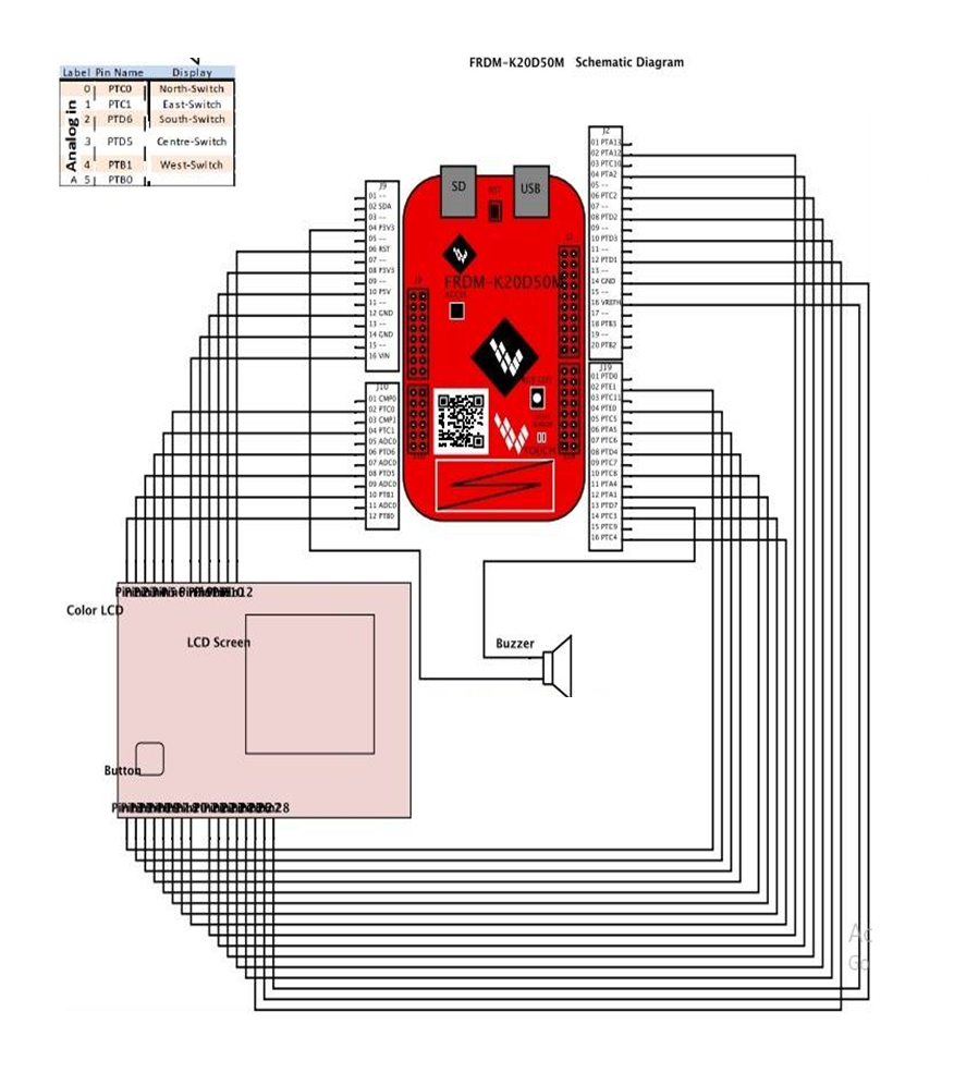
The music box is being designed which is able to play a song as the alarm tune, which is implemented by using the kinetics K-20 microcontroller, five-way switch and the132x132 RGB LCD screen. Interrupts are used to instruct the microprocessor to do several tasks at once. The RTF timer module is used as the timer to produce a musical tone or a note.
The LCD panel is used to provide a graphical user interface to the user with a menu and sub-menus that is used to control the set time, set alarm, set data and select alarm tune. This also shows the time in both analogue and digital, along with the date and day of the week. The five way switch included is used as the input to scroll through the menus, select a menu and change the time, date, alarm tune, day of the week and the alarm tune. As the challenge, the lyrics of the song that is played as the alarm tune is being displayed on the LCD panel.
The LCD mini pad consist of both the LCD panel and the five-way switch, in which the LCD panel is the visual output and the five-way switch is the input that is used to control the functions provided on the output displayed on the LCD screen. The tune is played through the small piezo-electric transducer that is used as the sound output in this system.
Methodology1KHz Square Wave:
A square wave form of 1 kHz was generated and observed on the cathode-ray oscilloscope. The oscilloscope verifies the square waveform of 1 kHz.
Basic Clock:
A basic clock is implemented using the Freescale MK20 Freedom microcontroller. The colour LCD display is used in order to display the clock in an attractive fashion where the time shown in both analogue and digital way. Also the day of the week and the date is shown below the time. Different colours are used to enhance the visual display of the clock in an attractive fashion.
The 5-position switch provided on the LCD board is used to scroll through the menus and change the time and date according to the user’s preference.
The focus is on interrupts in order to implement the system, this reduces the usage of the processor in the hardware since interrupts are used instead of polling. This also speeds up the system and saves a lot of power. The RTC interrupts comes in handy, since it provides interrupts at a constant time interval of one second.
RTC refers to the Real Time Clock that comes with the hardware providing interrupts at 1 second interval. The RTC is driven at a 32 kHz crystals independent power supply. This is used to generate a 1 second resolution in out clock.
Main Function:
- Clock initialized.
- SMGC5 clock is enabled to all the ports.
- Lcd_initialise function is called to display the clock on the screen.
- LCD is cleared to refresh the screen.
- RTC is enabled.
Interrupt Routine:
§ RTC clock is used as the interrupts to generate one second pulses.
Date setting and Day:
Algorithm was used to determine the day of the week and to keep the date synchronized with the clock.
For the date, moths such as February must be considered since it has only 28 days for the months. The leap year phenomenon is what its called.
Structure Diagrams for the clock module:
Musical Alarm Clock:
Additional functions are added to the basic clock, where it is modified to work as an Alarm Clock. Visually, two menu options are added to the system where the user gets to set the alarm, and set the alarm tone from the hard coded 3 alarm tunes. The challenging part is, as the alarm is set off, the lyrics of the music is displayed synchronized with the music on the screen.
To accomplish this task, the use of FTM timer and Interrupts were very useful. For the music to be played, there are two factors to be considered. The timing for each and every note to be played which is at different time intervals, and the tempo to determine at which speed the melody is to be played.
To save the usage of the processor being used and the power consumption, the interrupts are used to determine the time at which each and every note is to be played and the tempo at which the song has to be played. Two channels of FTM timer interrupts are being used here. The FTM0 for the trimming of the notes, and the FTM1 to determine the speed at which the melody is to be played.
Each note is specified with a separate note, and timing value, this is used in creating interrupts to determine which note is to be played at what time, where the system is not required to poll after every note to create delays after every note.
Each note played has a different frequency value corresponding to its note and its octave. Different note produces a different musical note at the piezo-electric transducer according to the timing produced by the interrupts.
Output compare
The Interrupts used for playing the notes and the tempo uses the output compare. When the interrupts has occurred, TOF flag is raised, the output compare is then used to monitor which interrupt refers to which note.
The FTMx_CnV is a 16 bit register used to hold the output compare value that is to be compared. This signals a hit when an output compare event has occurred. CHF and CHIE are enabled at a hit and then the system waits for an interrupt to occur.
This program makes use of two FTM timer channels which are FTM0 and FTM 1 in this case. Clock time reaches alarm time, the musical tune will be played according to its specific number of beats and frequencies. The alarm can be set by the option available in the menu set alarm time.
5 Switches:
- Centre Switch – Pressed to select or set alarm off.
- North Switch – Right scroll.
- South Switch – Left scroll.
- West Switch – Up scroll.
- East Switch – Down scroll.
FTM0 channel 7 (Interrupt routine):
- Connected to piezo-electric transducer (Channel D7).
- Differentiate the note frequencies and play the tone.
- The Port D toggles once the note frequency is changed to the next.
- Print the lyrics of the songs synchronized with the notes.
- Clear the flag.
FTM 1 (Interrupt routine):
- Sets the tempo at which the note is played.
- The port toggles once the tick rate achieves the specific duration.
- The tune will be played continuously when the tune reaches the ending part.
- Clear the flag.
Flowchart for the Alarm Clock:
Structure diagrams for the Alarm clock:
Structure diagrams for the system:
Flowchart for the system:


Comments