


Software apps and online services | ||||||
| ||||||
 |
| |||||
Hand tools and fabrication machines | ||||||
 |
| |||||
 |
| |||||
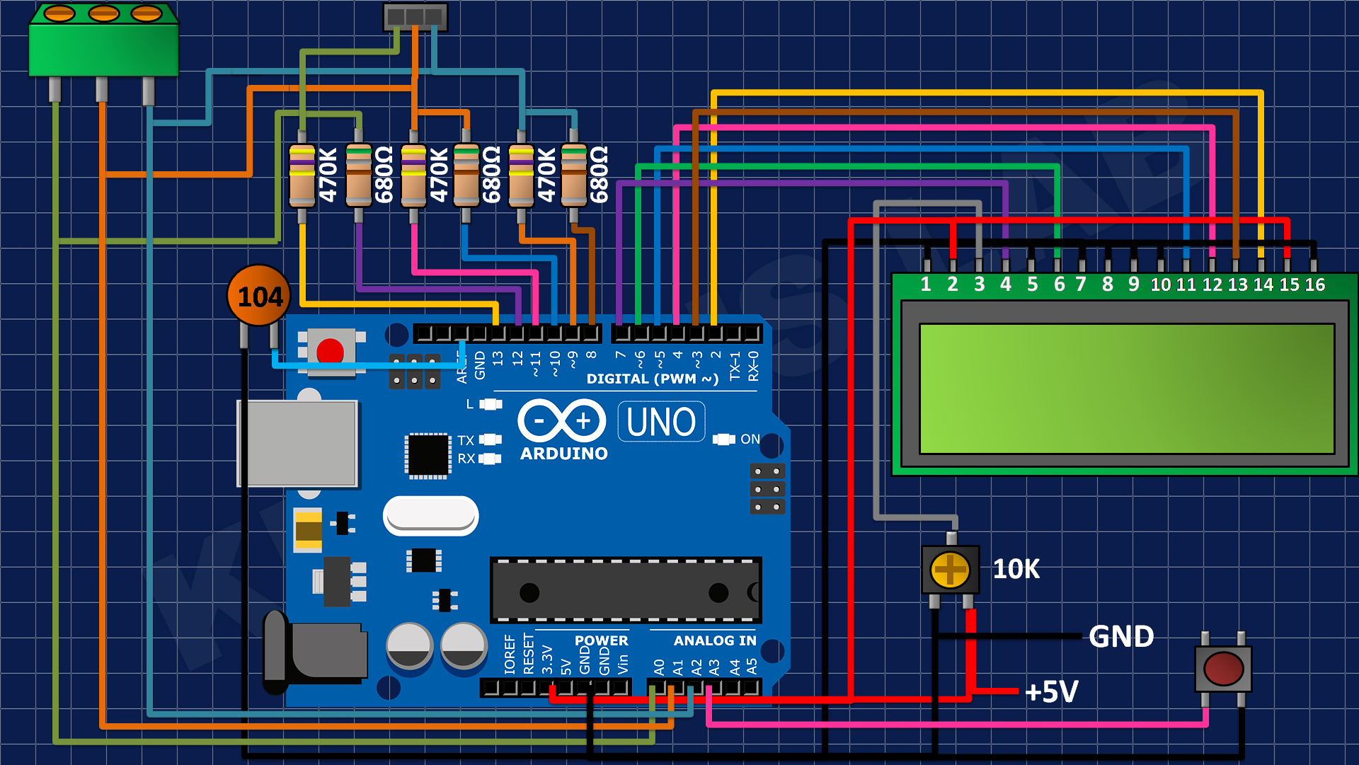
You might know component tester and its different versions made by many hobbyists. Today I have made a minimal version of this component tester, using some SMD components along with Through hole. I used Arduino Nano microcontroller as the brain of project. And after using a suitable resistor divider network you can get very accurate value of most of the components.
I want to keep it simple, so I choose 16x2 LCD screen. It is able to display all the graphics through symbols, numbers and alphabets. I am here for only sharing the experience in building nothing about the code. Code for this project can be downloaded from here. If you want to know more about the tester working and principle then refer to this 100-page manual. Which has all info about modes, screen types, Microcontrollers and software.
I made these PCB using PCBWAY prototyping service, starting from $5 for 5 PCB. I always use PCBway prototyping service for my projects to give them a better look and to reduce overall efforts. Sign-up to PCBWAY using this link to get free new user coupons.
Why minimal version:First, to reduce the overall cost of the system. And secondly many of the Ardu-tester Arduino code give error. But through this minimal system you can test different codes and then implement one in your next project. I am making this for test purpose that’s why I don’t use any battery. Real time on bench testing gives the real behavior of the project.
Components required:1) Arduino Nano
2) 16x2 LCD
3) 100nf capacitors
4) 1k resistor
5) 16Mhz crystal oscillator
6) 22pf capacitors
7) Type C charging jack
Circuit diagram:This version is limited to directly use with USB; this version doesn’t offer any protection against voltage. So, try to use a power bank or fixed value power module. A tactile button is connected to A3 pin of the Arduino which is used to reset the system and test.
Arduino SMD microcontroller with 16Mhz crystal and 22pf capacitor for impedance matching. 470K and 680 Ohms resistor divider network is given to the ADC of Arduino. These values can be calibrated inside the code also. I always to prefer to get a microcontroller chip directly from the top of Arduino Nano after burning sketch into it.
PCB designs:I made this minimal design using the above given modified schematics. You can download all the files and code from here. Programming headers are added on the back layer to change/ update the firmware.
I am using FR4 material, Hasl finish, white solder mask and 1.6mm thickness. A very thanks to PCBWAY for sponsoring this project. PCBway is one of leading PCB manufacturing company in China. Deals in PCB manufacturing, SMT assembly, PCBA, stencil, 3D- printing and CNC. Try out the more services from here now, and get free PCB coupons on first Sign-up using this link. Get your 5 pcs of PCB boards in just $5.
Code:Full code can be downloaded from here, try to install the latest libraries for the LCD. You can comment here, if found any problem in uploading the code. The code calls more than 10 files, so don’t get confuse with that only keep focus on Ardu-tester_1_13 and upload it using simple steps.
Working:This component tester can test all of the passive components and most of Active components. Like- Resistor, capacitor, inductor, Transistor, UJT, Mosfet, IGBT, Diode and LEDs. Here I made some tests using my version:
This version not only tells the value of component but also give a small usable datasheet like for a transistor its pins, configuration and gain can be obtained.
Testing Mosfet:
Testing Capacitor:
Testing Inductor:
You may refer to a YouTube channel named as eevblog who actually explained the working of resistor divider network and how wisely this meter is designed. Using a very less external circuit this meter covers almost every electronic component. The software is very optimized and thanks to maker to give us such an extraordinary device.
Ordering PCB from PCBWAY:PCBway has introduced a new plugin for the KICAD, now you can directly add your designed Gerber into PCBWAY cart. Here are few steps you may follow to add this plugin into your KICAD software.
Open the KICAD designer and click on plugin and content manager.
Write PCBWAY in repository then download and install the latest version.
To update the plugin in real time in editor, go to the tools menu and then to the external plugins, refresh the system, it will update the settings and then show a PCBWAY logo on the toolbar. Which redirects to PCBWAY webpage and upload the Gerbers directly.
We will reduce the overall connection by using a 12c module with 16x2 LCD. And a small battery with proper charging and protection features. And a new version of software to fix all the existing bugs and adds new features also with hardware.
ArduTester_1_13.ino
Arduino//Test with program in
#include <avr/io.h>
#include <util/delay.h>
#include <avr/sleep.h>
#include <stdlib.h>
#include "stdint.h" //JLG
#include <string.h>
#include <avr/eeprom.h>
#include <avr/pgmspace.h>
#include <avr/wdt.h>
#include <math.h>
#define MAIN_C
#include "Makefile.h" //JLG
#include "Transistortester.h"
#include "config.h"
#include "part_defs.h"
#include "lcd_routines.h"
#include "lcd_defines.h"
#include "wait1000ms.h"
#include "autoconf.h"
#include "tt_function.h"
#include "tt_resistor.h"
#include "bitmaps.h"
#include "font.h"
#include "24x32update_bitmaps.h"
/* defines global variables in RAM and EEprom from file tt_globals.h */
/* removed ifdef MAIN_C because always defined */
#define COMMON
#ifdef AUTO_CAL
const int8_t RefDiff EEMEM = REF_R_KORR; // correction of internal Reference Voltage
// const uint16_t cap_null EEMEM = C_NULL; // Zero offset of capacity measurement
const int16_t ref_offset EEMEM = REF_C_KORR; // default correction of internal reference voltage for capacity measurement
// the zero offset for capacity measurement for all pin combinations
// LoPin:HiPin 2:1 3:1 1:2 marker 3:2 1:3 2:3
const uint8_t c_zero_tab[] EEMEM = { C_NULL,C_NULL,C_NULL+TP2_CAP_OFFSET,C_NULL+2,C_NULL+TP2_CAP_OFFSET,C_NULL,C_NULL }; //table of zero offsets
// if the marker position of c_zero_tab is not equal the first position, the calibration has not run before
#endif
#ifdef SamplingADC
const uint16_t c_zero_tab2_lo[] EEMEM = { C_NULL*100,C_NULL*100,C_NULL*100,C_NULL*100,C_NULL*100,C_NULL*100,C_NULL*100 }; // zero offsets for SamplingADC capacitance measurement, in 0.01 pF, lo voltage
const uint16_t c_zero_tab2_hi[] EEMEM = { C_NULL*100,C_NULL*100,C_NULL*100,C_NULL*100,C_NULL*100,C_NULL*100,C_NULL*100 }; // same, hi voltage
#endif
#ifdef WITH_MENU
const int8_t big_cap_corr EEMEM = C_H_KORR; // default correction for big capacity measurement
#if defined(WITH_FREQUENCY_DIVIDER) && !defined(NO_FREQ_COUNTER)
#ifndef FREQ_SCALER
#define FREQ_SCALER 0 // 1<<0 = 1
#endif
const uint8_t f_scaler EEMEM = FREQ_SCALER; // default scaler for frequency measurement
#endif
#endif
const uint8_t EE_ESR_ZEROtab[] EEMEM = {ESR_ZERO, ESR_ZERO, ESR_ZERO, ESR_ZERO}; // zero offset of ESR measurement
#ifdef WITH_ROTARY_SWITCH
// const uint8_t EE_RotarySwitch EEMEM = 0; // rotation switch is not detected
#endif
#if ((LCD_ST_TYPE == 7565) || (LCD_ST_TYPE == 1306) || (LCD_ST_TYPE == 8812) || (LCD_ST_TYPE == 8814) || defined(LCD_DOGM))
const uint8_t EE_Volume_Value EEMEM = VOLUME_VALUE; // Volume Value for ST7565 controller
#endif
#ifdef LCD_CHANGE_COLOR
const uint8_t EE_BG_COLOR1 EEMEM = LCD_BG_COLOR & 0xff; // lower bits of background color
const uint8_t EE_BG_COLOR2 EEMEM = LCD_BG_COLOR >> 8; // higher bits of background color
const uint8_t EE_FG_COLOR1 EEMEM = LCD_FG_COLOR & 0xff; // lower bits of foreground color
const uint8_t EE_FG_COLOR2 EEMEM = LCD_FG_COLOR >> 8; // higher bits of foreground color
#endif
struct Diode_t {
uint8_t Anode[6];
uint8_t Cathode[6];
unsigned int Voltage[6];
};
COMMON struct Diode_t diodes;
struct Switch_t {
union {
unsigned long Pw; // combined Mask
uint8_t R[4]; // mask to switch a Pin with R_L, mask to switch a Pin with R_H
} Pin;
};
COMMON uint8_t NumOfDiodes;
COMMON uint8_t diode_sequence;
typedef struct {
unsigned long hfe; //current amplification factor
unsigned int uBE; //B-E-voltage of the Transistor or RDS for E-MOS; Idss for JFET
unsigned int current; // current of Drain in 1uA
unsigned int ice0; // for BJT ICEO in 1uA; for FET cut-off voltage in mV
unsigned int gthvoltage; //Gate-threshold voltage
// for bipolar gthvoltage is ICEs in 1uA
#define ices gthvoltage
// note: don't change the total size of the above fields, since the offsets of the following 3 fields are hard-coded in PinLayout.S
uint8_t b,c,e; //pins of the Transistor
uint8_t count;
}trans_t;
COMMON trans_t ptrans; // parameters of P type transistor
COMMON trans_t ntrans; // parameters of N type transistor
COMMON trans_t *_trans; // pointer to trans_t structure
COMMON uint8_t tmpval, tmpval2;
COMMON unsigned int ref_mv; //Reference-voltage in mV units (as read with ADC)
COMMON unsigned int ref_mv_offs; //Reference-voltage in mV units with eeprom offset for C
COMMON unsigned int adc_internal_reference; //internal reference voltage of ADC in mV units
COMMON unsigned int adc_vcc_reference; // reference voltage of ADC,if switched to VCC in mV units
COMMON unsigned int RHmultip; // Multiplier for capacity measurement with R_H (470KOhm)
#ifdef WITH_MENU
COMMON union t_frq{
unsigned long dw;
uint16_t w[2];
uint8_t b[4];
} ext_freq; // external frequency
//COMMON unsigned long ext_period;
COMMON unsigned int pinchange_count;
COMMON unsigned int pinchange_max;
#endif
COMMON struct cap_t {
// Attention! If you change this structure, you must also change defines in GetESR.S !!!!
unsigned long cval; // capacitor value
unsigned long cval_max; //capacitor with maximum value
union t_combi{
unsigned long dw; // capacity value without corrections
uint16_t w[2];
} cval_uncorrected;
#if FLASHEND > 0x1fff
unsigned int esr; // serial resistance of C in 0.01 Ohm
unsigned int v_loss; // voltage loss 0.1%
#endif
uint8_t ca, cb; //pins of capacitor
int8_t cpre; //Prefix for capacitor value -12=p, -9=n, -6=, -3=m
int8_t cpre_max; //Prefix of the biggest capacitor
} cap;
unsigned int cell_mv[3]; //remaining load voltages after discharge cycle
#ifndef INHIBIT_SLEEP_MODE
/* with sleep mode we need a global ovcnt16 */
COMMON volatile uint16_t ovcnt16;
COMMON volatile uint8_t unfinished;
#endif
COMMON int16_t load_diff; // difference voltage of loaded capacitor and internal reference
COMMON uint8_t WithReference; // Marker for found precision voltage reference = 1
COMMON uint8_t PartFound; // type of the found part
COMMON uint8_t PartMode; // description of the found part
COMMON char outval[10]; // String for ASCII-output i2lcd, u2lcd
//COMMON char OutBuffer[10]; // String for ASCII-output DisplayValue
COMMON uint8_t empty_count; // counter for max count of empty measurements
COMMON uint8_t mess_count; // counter for max count of nonempty measurements
COMMON struct ADCconfig_t {
uint8_t Samples; // number of ADC samples to take
uint8_t RefFlag; // save Reference type VCC of IntRef
uint16_t U_Bandgap; // Reference Voltage in mV
uint16_t U_AVCC; // Voltage of AVCC
} ADCconfig;
#ifdef AUTO_CAL
COMMON uint8_t pin_combination; // coded Pin-combination 2:1,3:1,1:2,x:x,3:2,1:3,2:3
COMMON uint16_t resis680pl; // port output resistance + 680
COMMON uint16_t resis680mi; // port output resistance + 680
COMMON uint16_t pin_rmi; // port output resistance to GND side, 0.1 Ohm units
COMMON uint16_t pin_rpl; // port output resistance to VCC side, 0.1 Ohm units
COMMON uint8_t UnCalibrated; // 0, if the tester is calibrated
#endif
#ifdef WITH_ROTARY_SWITCH
#define ROT_MSK 0x03 /* must be power of two - 1: 3,7,15 */
struct Rotary_t {
uint8_t state[(ROT_MSK+1)]; // coded state history of the rotatry switch, bit 0 == state of A-switch, bit 1 = state of B-switch
uint8_t ind; // index to the last entry of the state history (rotary switch)
int8_t count; // count of right steps, negative if left steps
uint8_t incre; // absolute value of step count
#if WITH_ROTARY_SWITCH == 4
// no rotary switch connected, UP and DOWN key is present
uint8_t a_state; // history of switch A state for single UP switch
uint8_t b_state; // history of switch B state for single DOWN switch
#endif
};
COMMON struct Rotary_t rotary;
COMMON uint8_t rotary_switch_present; // is set to 1, if rotary switch movement is detected
// COMMON const uint8_t EE_RotarySwitch; // rotation switch is detected
#endif
#if FLASHEND > 0x1fff
COMMON uint8_t DC_Pwr_mode;
#endif
COMMON uint8_t lcd_text_line;
COMMON uint8_t _lcd_column;
COMMON uint8_t last_line_used;
//#if POWER_OFF+0 > 1
COMMON unsigned int display_time; // display time of measurement in ms units
//#endif
#if (LCD_ST_TYPE == 7920)
COMMON uint8_t lcd_bit_mem[64][16];
#endif
#if ((LCD_ST_TYPE == 7565) || (LCD_ST_TYPE == 1306) || defined(LCD_DOGM))
COMMON const uint8_t EE_Volume_Value EEMEM; // Volume Value for ST7565 controller
#endif
#ifdef LCD_CHANGE_COLOR
COMMON union {
uint16_t w;
uint8_t b[2];
} lcd_bg_color;
#endif
#if defined(LCD_CHANGE_COLOR) || defined(LCD_ICON_COLOR)
COMMON union {
uint16_t w;
uint8_t b[2];
} lcd_fg_color;
#endif
#if defined(LCD_ICON_COLOR)
COMMON union {
uint16_t w;
uint8_t b[2];
} lcd_fg2_color;
#endif
/* END defines global variables in RAM and EEprom from file tt_globals.h */
#ifndef INHIBIT_SLEEP_MODE
// prepare sleep mode
EMPTY_INTERRUPT(TIMER2_COMPA_vect);
#endif
#if !defined(INHIBIT_SLEEP_MODE) || defined(SamplingADC)
// ADC_vect is always required by samplingADC()
EMPTY_INTERRUPT(ADC_vect);
#endif
/**************************************************
*** begin of transistortester program
***************************************************/
void setup() {
#ifdef WITH_HARDWARE_SERIAL
Serial.begin(115200); // Serial Monitor
#endif
//#ifdef ARDUINO_UNO
// pinMode(A3,INPUT_PULLUP);// avoids external 10K Pullup
//#endif
uint8_t ii;
unsigned int max_time;
#ifdef SEARCH_PARASITIC
unsigned long n_cval; // capacitor value of NPN B-E diode, for deselecting the parasitic Transistor
int8_t n_cpre; // capacitor prefix of NPN B-E diode
#endif
#ifdef WITH_GRAPHICS
unsigned char options;
#endif
uint8_t vak_diode_nr; // number of the protection diode of BJT
union {
uint16_t pw;
uint8_t pb[2];
} rpins;
uint8_t x, y, z;
//switch on
ON_DDR = (1<<ON_PIN); // switch to output
ON_PORT = (1<<ON_PIN); // switch power on
#ifndef PULLUP_DISABLE
RST_PORT |= (1<<RST_PIN); // enable internal Pullup for Start-Pin
#endif
uint8_t tmp;
//ADC-Init
ADCSRA = (1<<ADEN) | AUTO_CLOCK_DIV; //prescaler=8 or 64 (if 8Mhz clock)
#ifdef __AVR_ATmega8__
// #define WDRF_HOME MCU_STATUS_REG
#define WDRF_HOME MCUCSR
#else
#define WDRF_HOME MCUSR
#if FLASHEND > 0x3fff
// probably was a bootloader active, disable the UART
UCSR0B = 0; // disable UART, if started with bootloader
#endif
#endif
wait500ms();
#if (PROCESSOR_TYP == 644) || (PROCESSOR_TYP == 1280)
#define BAUD_RATE 9600
// UBRR0H = (F_CPU / 16 / BAUD_RATE - 1) >> 8;
// UBRR0L = (F_CPU / 16 / BAUD_RATE - 1) & 0xff;
// UCSR0B = (1<<TXEN0);
// UCSR0C = (1<<USBS0) | (3<<UCSZ00); // 2 stop bits, 8-bit
// while (!(UCSR0A & (1<<UDRE0))) { }; // wait for send data port ready
#ifdef SWUART_INVERT
SERIAL_PORT &= ~(1<<SERIAL_BIT);
#else
SERIAL_PORT |= (1<<SERIAL_BIT);
#endif
SERIAL_DDR |= (1<<SERIAL_BIT);
#endif
tmp = (WDRF_HOME & ((1<<WDRF))); // save Watch Dog Flag
WDRF_HOME &= ~(1<<WDRF); //reset Watch Dog flag
wdt_disable(); // disable Watch Dog
#ifndef INHIBIT_SLEEP_MODE
// switch off unused Parts
#if PROCESSOR_TYP == 644
#ifdef PRUSART1
PRR0 = (1<<PRTWI) | (1<<PRSPI) | (1<<PRUSART1);
#else
PRR0 = (1<<PRTWI) | (1<<PRSPI) ;
#endif
// PRR1 = (1<<PRTIM3) ;
#elif PROCESSOR_TYP == 1280
PRR0 = (1<<PRTWI) | (1<<PRSPI) | (1<<PRUSART1);
PRR1 = (1<<PRTIM5) | (1<<PRTIM4) | (1<<PRTIM3) | (1<<PRUSART3) | (1<<PRUSART2) | (1<<PRUSART3);
#else
PRR = (1<<PRTWI) | (1<<PRSPI) | (1<<PRUSART0);
#endif
// disable digital inputs of Analog pins, but TP1-3 digital inputs must be left enabled for VGS measurement
DIDR0 = ((1<<ADC5D) | (1<<ADC4D) | (1<<ADC3D) | (1<<ADC2D) | (1<<ADC1D) | (1<<ADC0D)) & ~((1<<TP3) | (1<<TP2) | (1<<TP1));
TCCR2A = (0<<WGM21) | (0<<WGM20); // Counter 2 normal mode
TCCR2B = CNTR2_PRESCALER; //prescaler set in autoconf
#endif /* INHIBIT_SLEEP_MODE */
sei(); // enable interrupts
lcd_init(); //initialize LCD
// ADC_PORT = TXD_VAL;
// ADC_DDR = TXD_MSK;
if(tmp) {
// check if Watchdog-Event
// this happens, if the Watchdog is not reset for 2s
// can happen, if any loop in the Program doen't finish.
lcd_line1();
lcd_MEM_string(TestTimedOut); //Output Timeout
wait_about3s(); // time to read the Timeout message
switch_tester_off();
return 0;
}
#ifdef PULLUP_DISABLE
#ifdef __AVR_ATmega8__
SFIOR = (1<<PUD); // disable Pull-Up Resistors mega8
#else
MCUCR = (1<<PUD); // disable Pull-Up Resistors mega168 family
#endif
#endif
//#if POWER_OFF+0 > 1
// tester display time selection
#ifndef USE_EEPROM
EE_check_init(); // init EEprom, if unset
#endif
#ifdef WITH_ROTARY_SWITCH
// rotary_switch_present = eeprom_read_byte(&EE_RotarySwitch);
rotary.ind = ROT_MSK+1; //initilize state history with next call of check_rotary()
#endif
#ifdef WITH_HARDWARE_SERIAL
// ii = 60;
ii = 30;
#else
#if 1
for (ii=0; ii<60; ii++) {
if (RST_PIN_REG & (1 << RST_PIN))
break; // button is released
wait_about10ms();
}
#else
ii = 0;
if (!(RST_PIN_REG & (1<<RST_PIN))) {
// key is still pressed
ii = wait_for_key_ms(700);
}
#endif
display_time = OFF_WAIT_TIME; // LONG_WAIT_TIME for single mode, else SHORT_WAIT_TIME
if (ii > 30) {
display_time = LONG_WAIT_TIME; // ... set long time display anyway
}
#endif // WITH_HARDWARE_SERIAL
#if POWER_OFF+0 > 1
empty_count = 0;
mess_count = 0;
#endif
ADCconfig.RefFlag = 0;
Calibrate_UR(); // get Ref Voltages and Pin resistance
#ifdef WDT_enabled
wdt_enable(WDTO_2S); //Watchdog on
#endif
#ifdef WITH_MENU
if (ii >= 60) {
while(function_menu()); // selection of function
}
#endif
//*****************************************************************
//Entry: if start key is pressed before shut down
loop_start:
#if ((LCD_ST_TYPE == 7565) || (LCD_ST_TYPE == 1306))
lcd_command(CMD_DISPLAY_ON);
lcd_command(CMD_SET_ALLPTS_NORMAL); // 0xa4
#endif
lcd_clear(); // clear the LCD
ADC_DDR = TXD_MSK; // activate Software-UART
init_parts(); // reset parts info to nothing found
Calibrate_UR(); // get Ref Voltages and Pin resistance
lcd_line1(); // Cursor to 1. row, column 1
#ifdef BAT_CHECK
// Battery check is selected
Battery_check();
#else
lcd_MEM_string(VERSION_str); // if no Battery check, Version .. in row 1
#endif /* BAT_CHECK */
// begin tests
#if FLASHEND > 0x1fff
if (WithReference) {
/* 2.5V precision reference is checked OK */
#if POWER_OFF+0 > 1
if ((mess_count == 0) && (empty_count == 0))
#endif
{
/* display VCC= only first time */
lcd_line2();
lcd_MEM_string(VCC_str); // VCC=
Display_mV(ADCconfig.U_AVCC,3); // Display 3 Digits of this mV units
lcd_refresh(); // write the pixels to display, ST7920 only
wait_about1s(); // time to read the VCC= message
}
}
#endif
#ifdef WITH_VEXT
unsigned int Vext;
// show the external voltage
while (!(RST_PIN_REG & (1<<RST_PIN))) {
lcd_clear_line2();
lcd_MEM_string(Vext_str); // Vext=
ADC_DDR = 0; //deactivate Software-UART
Vext = W5msReadADC(TPext); // read external voltage
// ADC_DDR = TXD_MSK; //activate Software-UART
uart_newline(); // MAURO replaced uart_putc(' ') by uart_newline(), 'Z'
#if EXT_NUMERATOR <= (0xffff/U_VCC)
Display_mV(Vext*EXT_NUMERATOR/EXT_DENOMINATOR,3); // Display 3 Digits of this mV units
#else
DisplayValue((unsigned long)Vext*EXT_NUMERATOR/EXT_DENOMINATOR,-3,'V',3); // Display 3 Digits of this mV units
#endif
lcd_refresh(); // write the pixels to display, ST7920 only
wait_about300ms(); // delay to read the Vext= message
}
#endif /* WITH_VEXT */
#ifndef DebugOut
lcd_line2(); //LCD position row 2, column 1
#endif
EntladePins(); // discharge all capacitors!
if(PartFound == PART_CELL) {
lcd_clear();
lcd_MEM_string(Cell_str); // display "Cell!"
#if FLASHEND > 0x3fff
lcd_line2(); // use LCD line 2
Display_mV(cell_mv[0],3);
lcd_space();
Display_mV(cell_mv[1],3);
lcd_space();
Display_mV(cell_mv[2],3);
#endif
#ifdef WITH_SELFTEST
lcd_refresh(); // write the pixels to display, ST7920 only
wait_about2s();
AutoCheck(0x11); // full Selftest with "Short probes" message
#endif
goto tt_end;
}
#ifdef WITH_SELFTEST
#ifdef AUTO_CAL
lcd_cursor_off();
UnCalibrated = (eeprom_read_byte(&c_zero_tab[3]) - eeprom_read_byte(&c_zero_tab[0]));
if (UnCalibrated != 0) {
// if calibrated, both c_zero_tab values are identical! c_zero_tab[3] is not used otherwise
lcd_cursor_on();
}
#endif
#ifdef WITH_MENU
AutoCheck(0x00); //check, if selftest should be done, only calibration
#else
AutoCheck(0x01); //check, if selftest should be done, full selftest without MENU
#endif
#endif
#if FLASHEND > 0x1fff
lcd_clear_line2(); //LCD position row2, column 1
#else
lcd_line2(); //LCD position row2, column 1
#endif
lcd_MEM_string(TestRunning); //String: testing...
lcd_refresh(); // write the pixels to display, ST7920 only
#ifdef WITH_UART
uart_putc(0x03); // ETX, start of new measurement
uart_newline(); // MAURO Added
#endif
//
// check all 6 combinations for the 3 pins
// High Low Tri
CheckPins(TP1, TP2, TP3);
CheckPins(TP2, TP1, TP3);
CheckPins(TP1, TP3, TP2);
CheckPins(TP3, TP1, TP2);
CheckPins(TP2, TP3, TP1);
CheckPins(TP3, TP2, TP1);
// Capacity measurement is only possible correctly with two Pins connected.
// A third connected pin will increase the capacity value!
// if(((PartFound == PART_NONE) || (PartFound == PART_RESISTOR) || (PartFound == PART_DIODE)) ) {
if(PartFound == PART_NONE) {
// If no part is found yet, check separate if is is a capacitor
#ifdef DebugOut
lcd_data('C');
#endif
EntladePins(); // discharge capacities
//measurement of capacities in all 3 combinations
ReadCapacity(TP3, TP1);
#ifdef DebugOut
lcd_data('K');
#endif
#if DebugOut != 10
ReadCapacity(TP3, TP2);
#ifdef DebugOut
lcd_data('K');
#endif
ReadCapacity(TP2, TP1);
#ifdef DebugOut
lcd_data('K');
#endif
#endif
}
#ifdef WITH_UJT
// check for UJT
if (PartFound==PART_DIODE
&& NumOfDiodes==2 // UJT is detected as 2 diodes E-B1 and E-B2...
// && ResistorsFound==1 // ...and a resistor B1-B2
&& diodes.Anode[0]==diodes.Anode[1] // check diodes have common anode
// && (unsigned char)(ResistorList[0]+diodes.Anode[0])==2 // and resistor is between cathodes
)
// note: there also exist CUJTs (complementary UJTs); they seem to be (even) rarer than UJTs, and are not supported for now
{
CheckUJT();
}
#endif /* defined WITH_UJT */
#ifdef WITH_XTAL
if (PartFound==PART_NONE || ((PartFound==PART_CAPACITOR) && (cap.cpre_max == -12))) {
// still not recognized anything? then check for ceramic resonator or crystal
// these tests are time-consuming, so we do them last, and only on TP1/TP3
sampling_test_xtal();
}
#endif
//All checks are done, output result to display
#ifdef DebugOut
// only clear two lines of LCD
lcd_clear_line1();
#else
lcd_clear(); // clear total display
#endif
_trans = &ntrans; // default transistor structure to show
if (PartFound == PART_THYRISTOR) {
#ifdef WITH_GRAPHICS
lcd_big_icon(THYRISTOR|LCD_UPPER_LEFT);
lcd_draw_trans_pins(-8, 16);
lcd_set_cursor(0,TEXT_RIGHT_TO_ICON); // position behind the icon, Line 1
lcd_MEM_string(Thyristor); //"Thyristor"
#else
lcd_MEM_string(Thyristor); //"Thyristor"
PinLayout(Cathode_char,'G','A'); // CGA= or 123=...
#endif
goto TyUfAusgabe;
}
if (PartFound == PART_TRIAC) {
#ifdef WITH_GRAPHICS
lcd_big_icon(TRIAC|LCD_UPPER_LEFT);
lcd_draw_trans_pins(-8, 16);
lcd_set_cursor(0,TEXT_RIGHT_TO_ICON); // position behind the icon, Line 1
lcd_MEM_string(Triac); //"Triac"
#else
lcd_MEM_string(Triac); //"Triac"
PinLayout('1','G','2'); // CGA= or 123=...
#endif
goto TyUfAusgabe;
}
#ifdef WITH_PUT
if (PartFound == PART_PUT) {
static const unsigned char PUT_str[] MEM_TEXT = "PUT";
lcd_MEM_string(PUT_str);
_trans=&ptrans;
PinLayout('A','G',Cathode_char);
goto TyUfAusgabe;
}
#endif
#ifdef WITH_UJT
if (PartFound == PART_UJT) {
static const unsigned char UJT_str[] MEM_TEXT = "UJT";
lcd_MEM_string(UJT_str);
PinLayout('1','E','2');
#ifdef SamplingADC
static const unsigned char eta_str[] MEM_TEXT = " eta=";
lcd_next_line(0);
ResistorChecked[ntrans.e - TP_MIN + ntrans.c - TP_MIN - 1] = 0; // forget last resistance measurement
GetResistance(ntrans.c, ntrans.e); // resistor value is in ResistorVal[resnum]
DisplayValue(ResistorVal[ntrans.e - TP_MIN + ntrans.c - TP_MIN - 1],-1,LCD_CHAR_OMEGA,2);
lcd_MEM_string(eta_str); //"eta="
DisplayValue(ntrans.gthvoltage,0,'%',3);
#else /* ! SamplingADC */
static const unsigned char R12_str[] MEM_TEXT = "R12=";
lcd_next_line(0);
lcd_MEM_string(R12_str); //"R12="
DisplayValue(ResistorVal[ntrans.e - TP_MIN + ntrans.c - TP_MIN - 1],-1,LCD_CHAR_OMEGA,2);
lcd_data(',');
DisplayValue(((RR680PL * (unsigned long)(ADCconfig.U_AVCC - ntrans.uBE)) / ntrans.uBE)-RRpinPL,-1,LCD_CHAR_OMEGA,3);
#endif /* SamplingADC */
goto tt_end;
}
#endif /* WITH_UJT */
if (PartFound == PART_CAPACITOR) {
#if FLASHEND > 0x3fff
if ((cap.ca + cap.cb) == (TP1 + TP3)) {
show_Cap13(); // repeated capacity measurement
goto shut_off; // key was pressed or timeout
}
show_cap(0); // show capacity in normal way and measure additional parameters
#else
show_cap_simple(); // show capacity in normal way and measure additional parameters
#endif
goto tt_end;
} /* end PartFound == PART_CAPACITOR */
#ifdef WITH_XTAL
if (PartFound == PART_CERAMICRESONATOR) {
// static const unsigned char cerres_str[] MEM_TEXT = "Cer.resonator ";
lcd_MEM_string(cerres_str);
if (sampling_measure_xtal()) goto loop_start;
goto tt_end;
}
if (PartFound == PART_XTAL) {
// static const unsigned char xtal_str[] MEM_TEXT = "Crystal ";
lcd_MEM_string(xtal_str);
if (sampling_measure_xtal()) goto loop_start;
goto tt_end;
}
#endif
// ========================================
if(PartFound == PART_DIODE) {
// ========================================
if(NumOfDiodes == 1) { //single Diode
// lcd_MEM_string(Diode); //"Diode: "
#if FLASHEND > 0x1fff
// enough memory (>8k) to sort the pins and additional Ir=
DiodeSymbol_withPins(0);
GetIr(diodes.Cathode[0],diodes.Anode[0]); // measure and output Ir=x.xuA
#else
// too less memory to sort the pins
DiodeSymbol_withPins(0);
#endif
UfAusgabe(0x70); // mark for additional resistor and output Uf= in line 2
#ifndef SamplingADC
/* load current of capacity is (5V-1.1V)/(470000 Ohm) = 8298nA */
ReadCapacity(diodes.Cathode[0],diodes.Anode[0]); // Capacity opposite flow direction
if (cap.cpre < -3) { /* capacity is measured */
#if (LCD_LINES > 2)
lcd_line3(); // output Capacity in line 3
#endif
lcd_MEM_string(Cap_str); //"C="
#if LCD_LINE_LENGTH > 16
DisplayValue(cap.cval,cap.cpre,'F',3);
#else
DisplayValue(cap.cval,cap.cpre,'F',2);
#endif
}
#else // SamplingADC
showdiodecap:
cap.cval=sampling_cap(diodes.Cathode[0],diodes.Anode[0],0); // at low voltage
lcd_next_line_wait(0); // next line, wait 5s and clear line 2
DisplayValue(cap.cval,sampling_cap_pre,'F',2);
#ifdef PULLUP_DISABLE
lcd_data('-');
cap.cval=sampling_cap(diodes.Cathode[0],diodes.Anode[0],1); // at high voltage
if (cap.cval < 0) cap.cval = 0; // don't show negativ value
DisplayValue(cap.cval,sampling_cap_pre,'F',2);
#if LCD_LINE_LENGTH > 16
lcd_MEM_string(AT05volt); // " @0-5V"
#else
lcd_MEM_string(AT05volt+1); // "@0-5V"
#endif
uart_newline(); // MAURO Diode ('A')
#else
#warning Capacity measurement from high to low not possible for diodes without PULLUP_DISABLE option!
#endif /* PULLUP_DISABLE */
#endif
goto end3;
} else if(NumOfDiodes == 2) { // double diode
lcd_data('2');
lcd_MEM_string(Dioden); //"diodes "
if(diodes.Anode[0] == diodes.Anode[1]) { //Common Anode
DiodeSymbol_CpinApin(0); // 1-|<-2
DiodeSymbol_ACpin(1); // ->|-3
UfAusgabe(0x01);
#ifdef SamplingADC
goto showdiodecap; // double diodes are often varicap; measure capacitance of one of them
#else
goto end3;
#endif
}
if(diodes.Cathode[0] == diodes.Cathode[1]) { //Common Cathode
DiodeSymbol_ApinCpin(0); // 1->|-2
DiodeSymbol_CApin(1); // -|<-3
UfAusgabe(0x01);
#ifdef SamplingADC
goto showdiodecap; // double diodes are often varicap; measure capacitance of one of them
#else
goto end3;
#endif
// else if ((diodes.Cathode[0] == diodes.Anode[1]) && (diodes.Cathode[1] == diodes.Anode[0]))
}
if (diodes.Cathode[0] == diodes.Anode[1]) {
// normaly two serial diodes are detected as three diodes, but if the threshold is high
// for both diodes, the third diode is not detected.
// can also be Antiparallel
diode_sequence = 0x01; // 0 1
SerienDiodenAusgabe();
goto end3;
}
if (diodes.Cathode[1] == diodes.Anode[0]) {
diode_sequence = 0x10; // 1 0
SerienDiodenAusgabe();
goto end3;
}
} else if(NumOfDiodes == 3) {
//Serial of 2 Diodes; was detected as 3 Diodes
diode_sequence = 0x33; // 3 3
/* Check for any constellation of 2 serial diodes:
Only once the pin No of anyone Cathode is identical of another anode.
two diodes in series is additionally detected as third big diode.
*/
if (diodes.Cathode[0] == diodes.Anode[1]) {
diode_sequence = 0x01; // 0 1
}
if (diodes.Anode[0] == diodes.Cathode[1]) {
diode_sequence = 0x10; // 1 0
}
if (diodes.Cathode[0] == diodes.Anode[2]) {
diode_sequence = 0x02; // 0 2
}
if (diodes.Anode[0] == diodes.Cathode[2]) {
diode_sequence = 0x20; // 2 0
}
if (diodes.Cathode[1] == diodes.Anode[2]) {
diode_sequence = 0x12; // 1 2
}
if (diodes.Anode[1] == diodes.Cathode[2]) {
diode_sequence = 0x21; // 2 1
}
// if((ptrans.b<3) && (ptrans.c<3))
if(diode_sequence < 0x22) {
lcd_data('3');
lcd_MEM_string(Dioden); //"Diodes "
SerienDiodenAusgabe();
goto end3;
}
} // end (NumOfDiodes == 3)
lcd_MEM_string(Bauteil); //"Bauteil"
lcd_MEM_string(Unknown); //" unbek."
lcd_line2(); //2. row
lcd_data(NumOfDiodes + '0');
lcd_data('*');
lcd_MEM_string(AnKat_str); //"->|-"
lcd_MEM_string(Detected); //" detected"
goto not_known;
// end (PartFound == PART_DIODE)
// ========================================
} else if (PartFound == PART_TRANSISTOR) {
// ========================================
#ifdef SEARCH_PARASITIC
if ((ptrans.count != 0) && (ntrans.count !=0)) {
// Special Handling of NPNp and PNPn Transistor.
// If a protection diode is built on the same structur as the NPN-Transistor,
// a parasitic PNP-Transistor will be detected.
ReadCapacity(ntrans.e, ntrans.b); // read capacity of NPN base-emitter
n_cval = cap.cval; // save the found capacity value
n_cpre = cap.cpre; // and dimension
ReadCapacity(ptrans.b, ptrans.e); // read capacity of PNP base-emitter
// check if one hfe is very low. If yes, simulate a very low BE capacity
if ((ntrans.hfe < 500) && (ptrans.hfe >= 500)) n_cpre = -16; // set NPN BE capacity to low value
if ((ptrans.hfe < 500) && (ntrans.hfe >= 500)) cap.cpre = -16; // set PNP BE capacity to low value
if (((n_cpre == cap.cpre) && (cap.cval > n_cval))
|| (cap.cpre > n_cpre)) {
// the capacity value or dimension of the PNP B-E is greater than the NPN B-E
PartMode = PART_MODE_PNP;
} else {
PartMode = PART_MODE_NPN;
}
} /* end ((ptrans.count != 0) && (ntrans.count !=0)) */
#endif
// not possible for mega8, change Pin sequence instead.
if ((ptrans.count != 0) && (ntrans.count != 0)
&& (!(RST_PIN_REG & (1 << RST_PIN)))) {
// if the Start key is still pressed, use the other Transistor
#if 0
if (PartMode == PART_MODE_NPN) {
PartMode = PART_MODE_PNP; // switch to parasitic transistor
} else {
PartMode = PART_MODE_NPN; // switch to parasitic transistor
}
#else
PartMode ^= (PART_MODE_PNP - PART_MODE_NPN);
#endif
}
#ifdef WITH_GRAPHICS
lcd_set_cursor(0,TEXT_RIGHT_TO_ICON); // position behind the icon, Line 1
lcd_big_icon(BJT_NPN|LCD_UPPER_LEFT); // show the NPN Icon at lower left corner
if(PartMode == PART_MODE_NPN) {
// _trans = &ntrans; is allready selected a default
lcd_MEM_string(NPN_str); //"NPN "
if (ptrans.count != 0) {
lcd_data('p'); // mark for parasitic PNp
}
} else {
_trans = &ptrans; // change transistor structure
lcd_update_icon(bmp_pnp); // update for PNP
lcd_MEM_string(PNP_str); //"PNP "
if (ntrans.count != 0) {
lcd_data('n'); // mark for parasitic NPn
}
}
#else /* only character display */
if(PartMode == PART_MODE_NPN) {
// _trans = &ntrans; is allready selected a default
lcd_MEM_string(NPN_str); //"NPN "
if (ptrans.count != 0) {
lcd_data('p'); // mark for parasitic PNp
}
} else {
_trans = &ptrans; // change transistor structure
lcd_MEM_string(PNP_str); //"PNP "
if (ntrans.count != 0) {
lcd_data('n'); // mark for parasitic NPn
}
}
lcd_space();
#endif
// show the protection diode of the BJT
vak_diode_nr = search_vak_diode();
if (vak_diode_nr < 5) {
// no side of the diode is connected to the base, this must be the protection diode
#ifdef WITH_GRAPHICS
options = 0;
if (_trans->c != diodes.Anode[vak_diode_nr])
options |= OPT_VREVERSE;
lcd_update_icon_opt(bmp_vakdiode,options); // show the protection diode right to the Icon
#else /* only character display, show the diode in correct direction */
char an_cat; // diode is anode-cathode type
an_cat = 0;
#ifdef EBC_STYLE
#if EBC_STYLE == 321
// Layout with 321= style
an_cat = (((PartMode == PART_MODE_NPN) && (ntrans.c < ntrans.e)) ||
((PartMode != PART_MODE_NPN) && (ptrans.c > ptrans.e)));
#else
// Layout with EBC= style
an_cat = (PartMode == PART_MODE_NPN);
#endif
#else
// Layout with 123= style
an_cat = (((PartMode == PART_MODE_NPN) && (ntrans.c > ntrans.e))
|| ((PartMode != PART_MODE_NPN) && (ptrans.c < ptrans.e)));
#endif
if (an_cat) {
lcd_MEM_string(AnKat_str); //"->|-"
} else {
lcd_MEM_string(KatAn_str); //"-|<-"
}
#endif /* !WITH_GRAPHICS */
} /* endif vak_diode_nr < 6 */
#ifdef WITH_GRAPHICS
lcd_draw_trans_pins(-7, 16); // show the pin numbers
lcd_next_line(TEXT_RIGHT_TO_ICON); // position behind the icon, Line 2
lcd_MEM_string(hfe_str); //"B=" (hFE)
DisplayValue(_trans->hfe,-2,0,3);
lcd_next_line(TEXT_RIGHT_TO_ICON+1-LOW_H_SPACE); // position behind the icon+1, Line 3
lcd_data('I');
if (_trans->current >= 10000) {
lcd_data('e'); // emitter current has 10mA offset
_trans->current -= 10000;
} else {
lcd_data('c');
}
lcd_equal(); // lcd_data('=');
DisplayValue16(_trans->current,-6,'A',2); // display Ic or Ie current
lcd_next_line(TEXT_RIGHT_TO_ICON); // position behind the icon, Line 4
lcd_MEM_string(Ube_str); //"Ube="
Display_mV(_trans->uBE,3-LOW_H_SPACE);
last_line_used = 1;
#ifdef SHOW_ICE
if (_trans->ice0 > 0) {
lcd_next_line_wait(TEXT_RIGHT_TO_ICON-1-LOW_H_SPACE); // position behind the icon, Line 4 & wait and clear last line
lcd_MEM2_string(ICE0_str); // "ICE0="
DisplayValue16(_trans->ice0,-6,'A',2); // display ICEO
}
if (_trans->ices > 0) {
lcd_next_line_wait(TEXT_RIGHT_TO_ICON-1-LOW_H_SPACE); // position behind the icon, Line 4 & wait and clear last line
lcd_MEM2_string(ICEs_str); // "ICEs="
DisplayValue16(_trans->ices,-6,'A',2); // display ICEs
}
#endif
#else /* character display */
PinLayout('E','B','C'); // EBC= or 123=...
lcd_line2(); //2. row
lcd_MEM_string(hfe_str); //"B=" (hFE)
DisplayValue(_trans->hfe,-2,0,3);
#if FLASHEND > 0x1fff
lcd_space();
lcd_data('I');
if (_trans->current >= 10000) {
lcd_data('e'); // emitter current has 10mA offset
_trans->current -= 10000;
} else {
lcd_data('c');
}
lcd_equal(); // lcd_data('=');
DisplayValue16(_trans->current,-6,'A',2); // display Ic or Ie current
#endif
#if defined(SHOW_ICE)
lcd_next_line_wait(0); // next line, wait 5s and clear line 2
lcd_MEM_string(Ube_str); //"Ube="
Display_mV(_trans->uBE,3);
if (_trans->ice0 > 0) {
lcd_next_line_wait(0); // next line, wait 5s and clear line 2
lcd_MEM2_string(ICE0_str); // "ICE0="
DisplayValue16(_trans->ice0,-6,'A',3);
}
if (_trans->ices > 0) {
lcd_next_line_wait(0); // next line, wait 5s and clear line 2
lcd_MEM2_string(ICEs_str); // "ICEs="
DisplayValue16(_trans->ices,-6,'A',3);
}
#endif
#endif /* WITH_GRAPHICS */
#ifdef SHOW_VAKDIODE
if (vak_diode_nr < 5) {
lcd_next_line_wait(0); // next line, wait 5s and clear line 2/4
DiodeSymbol_withPins(vak_diode_nr);
lcd_MEM_string(Uf_str); //"Uf="
mVAusgabe(vak_diode_nr);
uart_newline(); // MAURO not verified ('D')
} /* end if (vak_diode_nr < 5) */
#endif
#ifdef WITH_GRAPHICS
PinLayoutLine('E','B','C'); // Pin 1=E ...
uart_newline(); // MAURO OK BJT ('E')
#endif
goto tt_end;
// end (PartFound == PART_TRANSISTOR)
// ========================================
} else if (PartFound == PART_FET) { /* JFET or MOSFET */
// ========================================
#ifdef WITH_GRAPHICS
unsigned char fetidx = 0;
lcd_set_cursor(0,TEXT_RIGHT_TO_ICON); // position behind the icon, Line 1
#endif
if((PartMode&P_CHANNEL) == P_CHANNEL) {
lcd_data('P'); //P-channel
_trans = &ptrans;
#ifdef WITH_GRAPHICS
fetidx = 2;
#endif
...
This file has been truncated, please download it to see its full contents.


Comments
Please log in or sign up to comment.