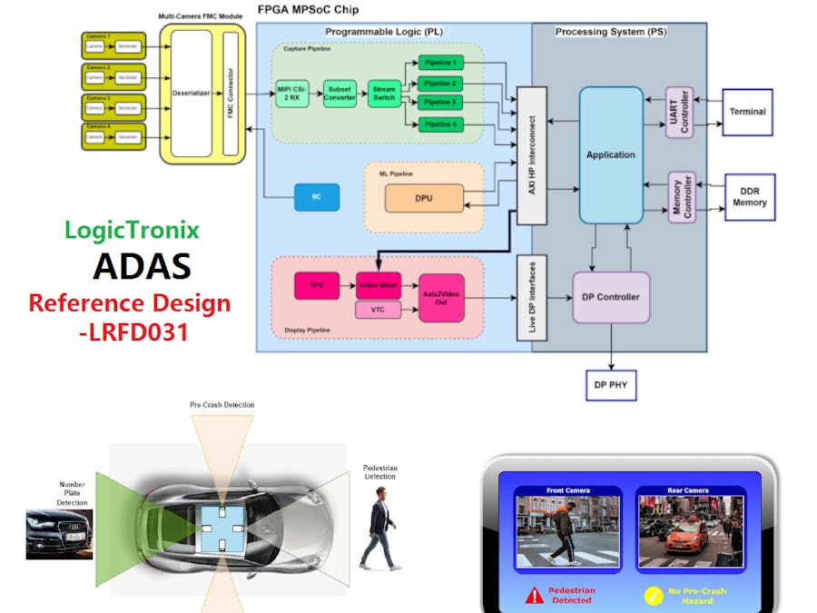
ADAS (Advanced Driving Assistance System) is highly popular in the Automobile Industry. The system has major functionality in that it assists drivers in order to avoid accidents and provides driver, vehicle and road safety. ADAS system now are major part of partial/conditional autonomous driving and fully autonomous driving.
This reference design is based on Xilinx Zynq UltraScale+ MPSoC-EV device based board in which we are going to run the Machine Learning Models (Vitis AI Models and Custom Models) using Vitis/Petalinux Method. This reference design is based on computer vision and machine learning approach, we use 4 GMSL camera system as a capture source and perform pre-processing, Machine learning deployments for person/pedestrian detection, rear view vehicle license plate detection and side view vehicle or object detection for vehicle safety.
The hardware used on this design was:
● Avnet Quad AR0231AT Camera FMC Bundle
● UltraZed-EV Carrier Card with UltraZed-EV SOM
Design tools used on this design was:
● Vivado 2020.2 or Later
● Petalinux 2020.2 or Later
● Vitis AI 1.3.1
ADAS System Design on Vitis/VIVADOThe above picture depicts the block diagrammatic view of ADAS FPGA hardware design. Avent Quad Cam FMC Module has a quad-cam deserializer IC that is capable of receiving up to 4 camera GMSL links. These links are deserialized and all four camera data are obtained by a common MIPI CSI-2 Interface. The data is transferred to FPGA by an FMC connector.
The PL side will have three pipelines design. These are expounded in the following sections:
Capture Pipeline:This pipeline is responsible for receiving the camera data, pre-processing the data, and writing data into memory. The pipeline consists of a series of blocks, namely, MIPI CSI-2 RX, Subset Converter, Stream Switch, and pre-processing pipeline block.
The camera data are obtained into FPGA by MIPI CSI-2 data format. These data are processed by the MIPI CSI-2 RX block, which then generates AXI stream data. The stream data width conversion is performed by Subset Converter Block. This block generates proper stream width for upcoming processing blocks. The Stream Switch block is used to demultiplex a single stream into four individual streams. This is so because the quad-cam deserializer is multiplexing four-camera data to a single MIPI CSI-2 interface. That’s why it is needed to be done demultiplexing in FPGA so as to access and process individual camera data further. Now each stream of data goes to four pre-processing pipeline blocks respectively.
The pipeline consists of a Bayer2RGB converter, Color Space Converter(CSC), scaling and Buffer Write blocks. The Bayer2RGB Converter converts the RAW format of sensor data into RGB format. The CSC block can convert RGB format into other formats, such as YUV. The Scaling block can do the scaling incoming video resolution into different output resolutions. The scaled resolutions will be utilized in the ML pipeline as well as the display pipeline.
Buffer write block is used to write the data into four separate locations of DDR memory, with a specific color format and resolution value. These memory locations will be accessed by the ML pipeline to retrieve the camera data and do the ML task.
ML PipelineThis design is following Vivado Flow, which means the DPU IP block is already been present in the Vivado Hardware Block Design.
We used 1xB4096 DPU IP configuration on this implementation to run the Machine Learning models.
In this design, the DPU core accesses first input stream frame from the memory. However, DPU can only take 640x480 resolution of frame. So, the resolution is downscaled by the scaling IP block. The DPU core then does the task, such as detection of specific objects in the frame, and that information are utilized by the application, running on APU, to show the detection and markings in the front and rear camera frame. This frame will become the final output, which is again stored in another memory location.
Our ML Pipeline runs following ML models:
○ Vehicle License Plate Recognition Model
○ Face detection
○ Pedestrian Detection
VIVADO hardware design:This pipeline contributes to showing off the processed camera data on the flat panel display on Vehicle dashboard. The video mixing block is the major block of this pipeline, which will read the ML processed data from the memory and show them as overlay layers. The resulting video data is converted into parallel video data by Axis2Video out the block. This block takes stream data and video timing as input and generates parallel video data. This data will be fed to Live Display Port(DP) interfaces.
HMI and GUIThe light-weight GUI, developed on QT framework, will be displayed in the FPD, where all four camera data, with detection information, will be displayed in a display unit using GST pipeline. The FPD creates the Human Machine Interface(HMI), from which users can get information as well as user can enter the information. On the other hand, the detection information can also be delivered to the user by visual color signs and text signaling. If detected, red-colored warnings and text can be displayed, and so on.
The current version, ADAS 1.0 is only based on four-camera inputs. The next version, ADAS 2.0 will have sensor fusion, such as LiDAR, and UltraSonic Sensor along with eight numbers of cameras to expand ADAS system capability and features to a greater extent.
Detail Reference Design can be found at: LogicTronix ADAS Reference Design
For any queries on LogicTronix ADAS, please write us at: info@logictronix.com
Kudos to our Senior Computer Vision Engineer Nikil Thapa for this insightful reference design!
About LogicTronix:LogicTronix is "Xilinx Certified Partner" and "Design Service Partner for Kria SoM-MPSoC for AI/ML Acceleration". LogicTronix provide "ML Accelerated Solutions" on Smart City, Surveillance, Secutiry, Automotive-ADAS, Computer Vision and HFT. Know more about us: https://www.xilinx.com/alliance/memberlocator/1-1dturdk.html


![LogicTronix [FPGA Design + Machine Learning Company]](https://hackster.imgix.net/uploads/attachments/1123066/_SyVIfEqFUU.blob?auto=compress%2Cformat&w=40&h=40&fit=min&dpr=2)


![LogicTronix [FPGA Design + Machine Learning Company]](https://hackster.imgix.net/uploads/attachments/1123066/_SyVIfEqFUU.blob?auto=compress%2Cformat&w=60&h=60&fit=min&dpr=2)


Comments
Please log in or sign up to comment.