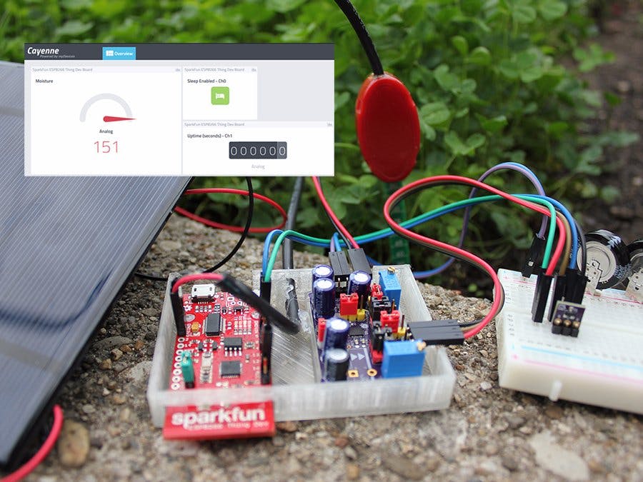
Energy is present everywhere -it just needs to be harvested- and the reason is simple: to free sensors and other modules from external power, making them energy autonomous to monitor and participate in many applications where cables or changing batteries are not part of an ideal solution.
With the help of Internet of Things (IoT) and energy harvesting devices, wireless communications can represent the ideal communication scenario to easily and reliably connect devices in a system by bringing network capability, data collection and management with little human intervention.
The IoT Solar Harvester simplifies a problem: harvesting energy from a solar panel by storing it in a rechargeable battery or super-capacitor, and then using it to power a sensor adding Internet capability to it.
Key Components- Solar panel: for this project, the energy harvester takes power from a 5V, 2.5W Solar panel.
- Energy Harvester: will gather and store the energy provided by the solar panel. Driven by the LTC3106 from Linear Technology, which is implemented in a custom made PCB, allowing some features of the chip to be programmed such as the output voltage (JP1), MPPC - Maximum Power Point Control (JP2 and VR2), Over/Under voltage threshold for the rechargeable backup battery (JP3), Low/High Current limit Input (JP4) and Input Turn On/Off thresholds (JP5 and VR1).
- Backup battery: excess input energy will be stored into one or more 1F 5.5V radial supercapacitors.
- IoT sensor: the SparkFun ESP8266 Thing - Dev Board provides IoT connectivity to a Vegetronix VH400 Soil moisture Sensor.
- Cayenne Software: used to monitor the data collected by the sensor (Ch4), the ESP8266 sleep setup (Ch0) and up-time (Ch1) -when sleep mode is not enabled-.
First of all you will need to solder some parts
- The energy harvester: most of the components of the custom PCB are SMD (requires the LTC3106 in QNF-20 package).
- A 2-pin male header is required for the JUMPER_EN on the SparkFun ESP8266 Thing - Dev Board, this way it can wake up itself from deep sleep mode, headers may me soldered to connect the sensor(s).
- The Solar panel may require wires to be soldered. I recommend to isolate its connections from the elements with some epoxy.
Once the soldering job is complete, all the modules can be assembled together with jumper wires following the IoT Energy Harvester main Schematic.
I've made a custom PCB for the LTC3106 (QFN-20) allowing its key features to be programmed by adjusting some Jumpers, the Potentiometers (VR1 and VR2) and the value of R2, which are explained in more detail in the LTC3106 IoT Energy Harvester PCB settings document.
For this project, the following settings were used.
- Output voltage to 3.3V (JP1).
- MPPC disabled (JP2) -this will ignore VR2 and R2-.
- Battery Over Voltage to 4V and Under Voltage (UV) to 2.78V (JP3)
- On/Off threshold on VIN (JP5)
- On/Off threshold set to 2.95V (VR1)
Depending on your setup, your settings may need adjustments.
To properly test the energy harvester, connect the load and the SOLAR input, then wait until the Super-capacitors are fully charged -once their voltage matches the Over Voltage threshold programmed (JP2)- then disconnect the SOLAR input; the load connected to the VOUT should keep working for a brief period.
LTC3106 Custom PCB detailed BOM- C1, C4, C5, C6: 330μF, 6.3V radial electrolytic capacitor (6.3mm diameter, through-hole)
- C2: 2.2µF, 10V ceramic Capacitor, 0603[1608]
- C3: 0.1μF, 6.3V ceramic capacitor 0603[1608]
- C7, C9: 1μF, 16V ceramic capacitor 0603[1608]
- C8: 100μF, 10V radial electrolytic capacitor (6.3mm diameter, through-hole)
- R1: 1Mohm, 1/10W, 1% resistor 0603[1608]
- R2: 820kohm resistor 0603[1608]
- R3: 33ohm resistor 0603[1608]
- VR1, VR2: 2Mohm trimmer potentiometer, through-hole
- D1: Schottky Diode ZLLS400 SOD-323
- D2: Zener Diode 5.1V SOD-323
- JP1, JP3: 2x3 through-hole header (2.54mm pitch)
- J3, JP2, JP4, JP5: 1x3 through-hole header (2.54mm pitch)
- J1, J2, JP6: 1x2 through-hole header (2.54mm pitch)
- L1: 10µH, minimum saturation current 750mA
- U1: Linear Technology LTC3106 (QFN-20)
- 2.54mm pitch, 2 position jumpers
If you feel that you are not ready for an SMT challenge and/or want to approach this project with a Breadboard, I'm also providing a breakout for the LTC3106 in its TSSOP-20 version.
For demonstration purposes, I've decided to store the excess energy into some super-capacitors but other battery chemistries could be used by changing the jumper JP3.
The ESP8266 only has one ADC input, but the I2C provides a good option to add more analog/digital sensors using a small/cheap micro-controller, similar to what I did on my Smart Modular Watering System with an ATtiny45.
Bypassing the voltage regulator and the FTDI chip of the ESP8266 Thing - Dev Board may improve the power consumption since the LTC3106 already has a 3.3V regulated output (JP1).
Using static IP is the best practice since this takes only a fraction of a second; when using DHCP, it takes the WiFi longer startup time and thus more power.
For more InformationFor more information visit www.linear.com/product/LTC3106


_3u05Tpwasz.png?auto=compress%2Cformat&w=40&h=40&fit=fillmax&bg=fff&dpr=2)


Comments
Please log in or sign up to comment.