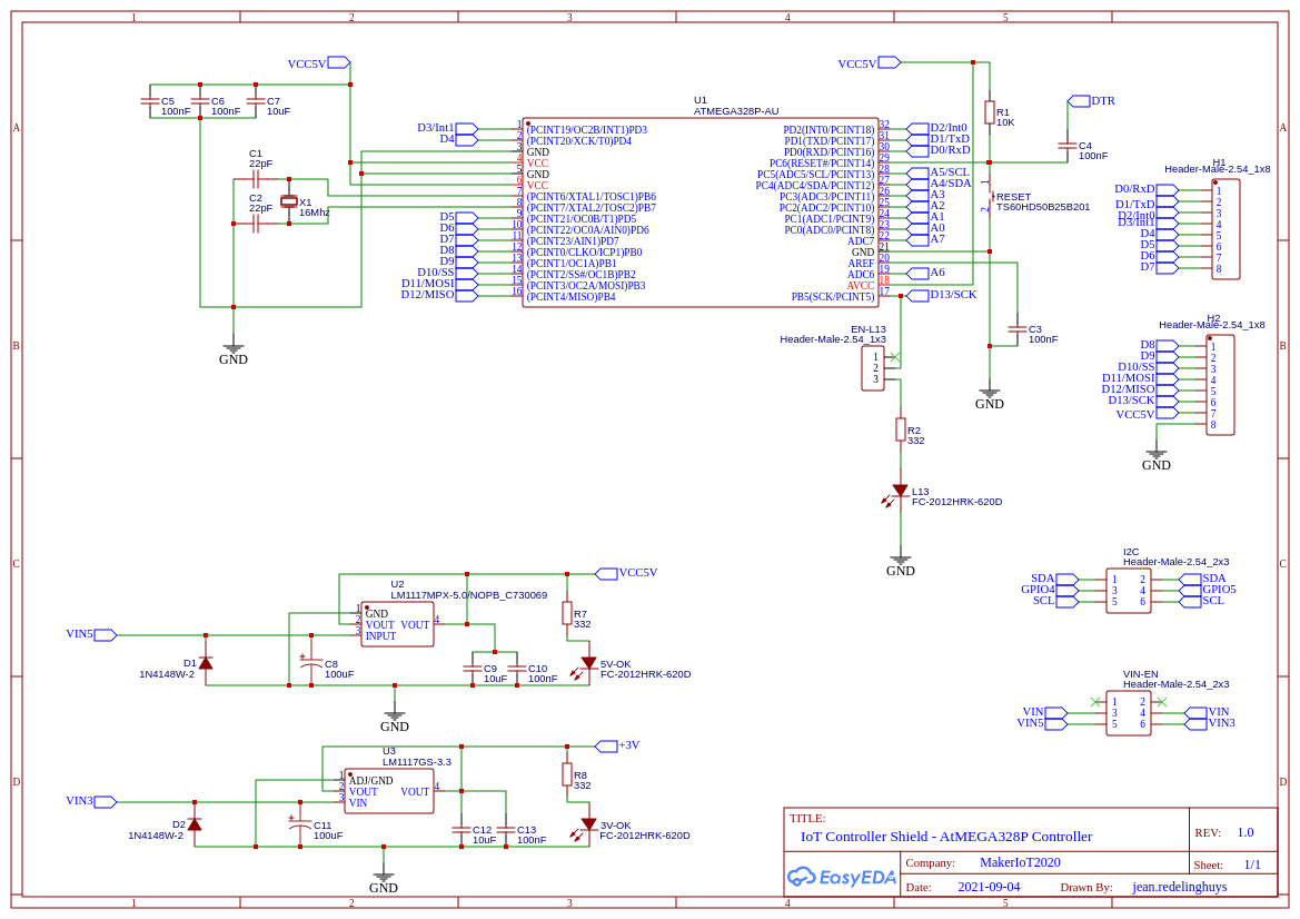
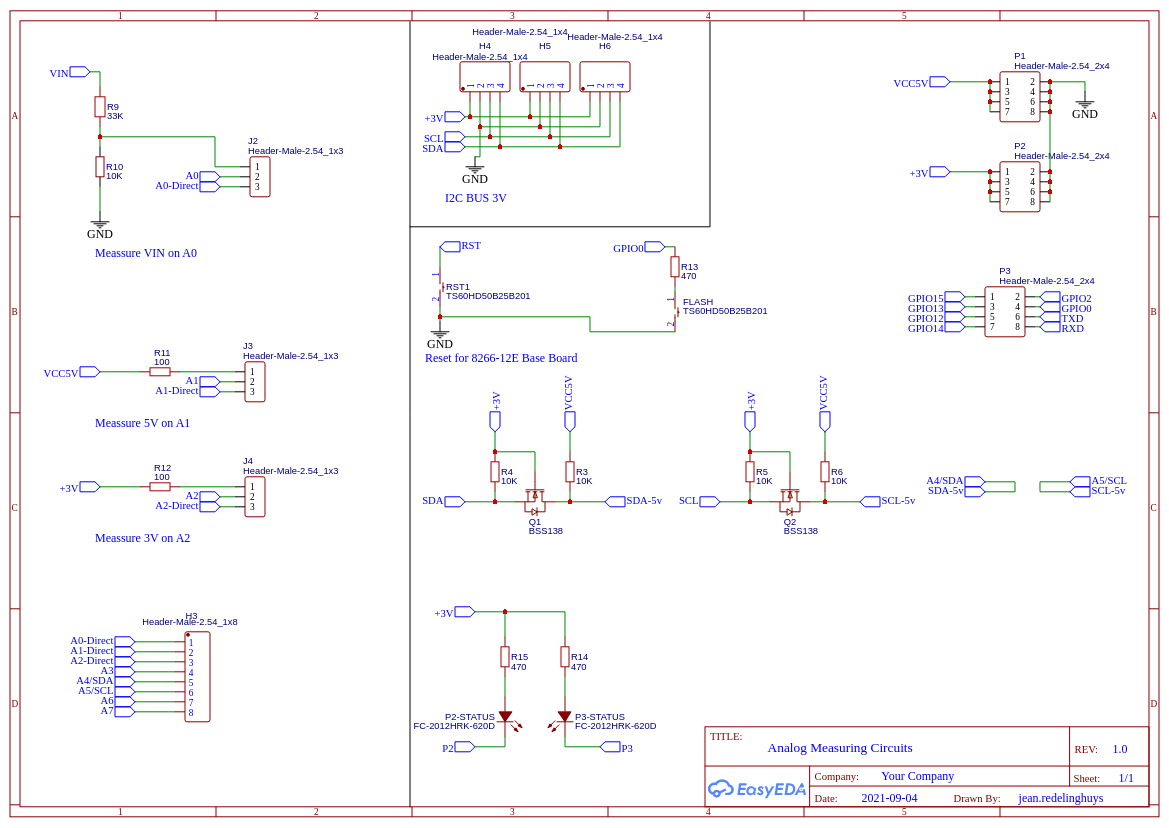
IntroductionAfter quite a few experiments, and playing with a lot of ideas, we have finally produced and tested an almost final prototype for the MCU-8266-12E IoT Controller Port Extender Card. While the baseboard already has quite a lot of free GPIO pins for additional sensors and devices, It did however have quite a few issues, namely a lack of sufficient Power outputs, difficulty access to the I2C bus, as well as only 2 relay outputs. Granted that you do have access to unused pins on the PCF8574 Port Extender, We nonetheless decided that an add-on card would definitely make sense to allow this device to really be more useable.While looking at various ideas for this card, the most flexible seemed to be the APE Protocol device as documented in ESPHome. They used a standard Arduino board for that, but we decided that, after testing it with an Arduino Nano, since it seems to work well, let us just design a dedicated PCB. It also looks much better as well
1). Dedicated LDO Regulators for 5v and 3.3v (800mA each), with jumpers to switch them on or off (receive power only from the IoT Motherboard).2.) Dedicated Logic Level Converter on the I2C Bus ( This is sort of very much needed 🙂 The Atmega 328P-AU is running at 5v on this device, to enable it to run at 16Mhz.. and the ESP8266 on the Motherboard is a 3.3v device..There are also 3x 3.3V I2C Headers, complete with 3.3v and Ground, as well as a single 5v I2C header3). 8 Analog Inputs ( While practically you can only use 6 of these if you use I2C )4). Voltage Divider provided on A0 to measure VIN ( to be safe, we calculated the resistors for 22v)5). 100R current limiting resistor on A1 and A2, to measure 5v and 3.3v as well…Analog inputs A0, A1 and A2 can be switched back to normal operation by changing the jumper at J2, J3 or J4 from On to Off.6). 12 Digital Inputs/Outputs (14 if you use D0 and D1 as well), as well as a Jumper to remove the LED on D13.7). Full access to the PCF8574 and ESP8266 Pins from the motherboard below.Uploading Code to the ATMega328PUploading code to the device requires the use of either an ISCP programmer ( Arduino as ISP works well ) or in the case of a pre-boot loaded chip, a USB-to-Serial converter. We did not find it necessary to add a dedicated USB-to-Serial converter onto the PCB. It is quite easy enough to do any flashing with the tools mentioned above.Make sure that the PCB is not stacked when doing this. ( This will prevent excessive current use of other components when you supply 5v to the PE card.
Procedure to upload using ICSP
During assembly, you are required to solder a single 90-degree bend pin header on the bottom side of the PCB, in the same hole as the board side edge of the RESET push-button. This will serve as the RESET Pin for the ISCP. Other connections are as follows:H2 Header <- > ICSP ProgrammerMOSI (E11~) – MOSI ( or Pin 11 on Arduino as ISP )MISO (E12 ) – MISO ( or Pin 12 on Arduino as ISP )SCK (E13) – D13 (or Pin 13 on Arduino as ISP )RESET – D10 (or Pin 10 on Arduino as ISP )
5v and Ground from Arduino as ISP or ISCP Programmer to any 5v and ground pin on the PE CardPlease note the description above for assembly of the RESET pin headerProcedure to upload using USB-to-Serial converterH1 HeaderE0/Rx <- to Tx of USB-to-Serial converterE1/Tx -> to Rx of USB-to-Serial converterH2 HeaderDTR <-> to DTR of USB-to-Serial converter [ This connection is needed for successful uploading. Don’t leave it out ]
5v and Ground from the USB-to-Serial converter to any 5v and ground pin on the PE Card


Comments
Please log in or sign up to comment.