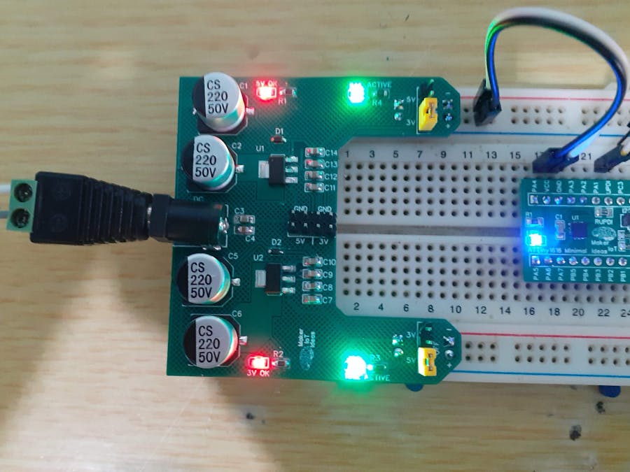
Breadboard Power modules are nothing new or exciting at all. I own a few commercial ones, and they are usually quite similar. They can be picked up for a few bucks and usually do what they are supposed to do, providing power to a project on a breadboard.
I decided to do my own version of one of these, as there were quite a few irritating flaws on all of the commercial versions that I have purchased over the years.
– They never fit my breadboard – This may seem strange, as I use a standard breadboard, but was never able to buy a power module that was a perfect fit.
– They contain unneeded components, like USB ports that take up a lot of space and a switch that all seem to fail in a very short time.
– The voltage regulators seem to all overheat, even at the minimum required input voltage
This got me to a point where I stopped using them at all, and started thinking about doing my own version. What I came up with, while not pretty, does exactly what I want it to, has decent smoothing capacitors on all power lines,
and does not overheat. I got rid of the switch, the bench power supply has a switch already, and also added LED status indicators for each rail, as well as the main DC power input.
The overheating problem was solved by giving the voltage regulators a big copper PCB heatsink each, which is many times the size of the actual regulator.That change, having used the same technique on many other PCBs before, immediately got rid of the heat issue, even at a 15v DC input, which is right at the maximum input voltage allowed.
The Custom designed Breadboard power module is however not perfect yet. on the cosmetic side, it is still not exactly symmetrical, with some weird irregular shapes on the PCB. This will be fixed in future, but for now, I am quite happy with its performance, which is actually all that I really care about.
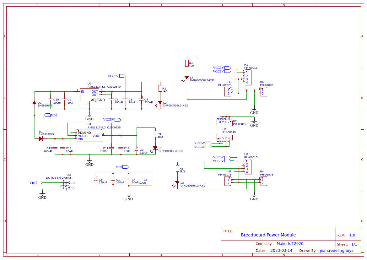
The SchematicThis is the schematic, which is straightforward, with nothing complicated. Two Low Dropout Voltage Regulators, AMS1117-3.3 and AMS1117-5.0 are individually fed from a 7-12v DC supply, with jumper selectable outputs of 3.3v or 5.0v on each of the Power rails. Led Indicators on each regulator output, as well as on the power rail outputs.
Smoothing capacitors are placed on the inputs and outputs of each regulator.
The resulting PCB is a two-layer board, with most power tracks routed on the top layer where possible. A solid (bottom) and hashed (top) ground plane ensures a proper ground connection. Big copper pours on the output of the regulators serves as PCB heatsinks, reducing the amount of heat generated quite significantly.
I choose PCBWay for my PCB manufacturing. Why? What makes them different from the rest?PCBWay‘s business goal is to be the most professional PCB manufacturer for prototyping and low-volume production work in the world. With more than a decade in the business, they are committed to meeting the needs of their customers from different industries in terms of quality, delivery, cost-effectiveness and any other demanding requests. As one of the most experienced PCB manufacturers and SMT Assemblers in China, they pride themselves to be our (the Makers) best business partners, as well as good friends in every aspect of our PCB manufacturing needs. They strive to make our R&D work easy and hassle-free.How do they do that?PCBWay is NOT a broker. That means that they do all manufacturing and assembly themselves, cutting out all the middlemen, and saving us money.PCBWay’s online quoting system gives a very detailed and accurate picture of all costs upfront, including components and assembly costs. This saves a lot of time and hassle.
PCBWay gives you one-on-one customer support, that answers you in 5 minutes ( from the Website chat ), or by email within a few hours ( from your personal account manager). Issues are really resolved very quickly, not that there are many anyway, but, as we are all human, it is nice to know that when a gremlin rears its head, you have someone to talk to that will do his/her best to resolve your issue as soon as possible.
Find out more here


Comments
Please log in or sign up to comment.