


Hardware components | ||||||
 |
| × | 1 | |||
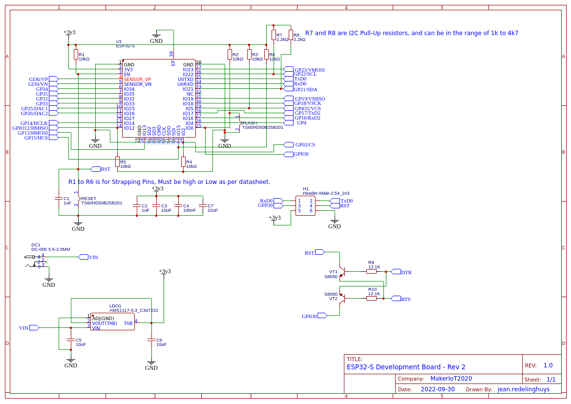
A few months ago, I started to work on an ESP32-S SOC module in Arduino Uno form factor. This is Revision 2.0 – the ESP32-S Dev Board – Rev 2.0
During the time since I designed, and ultimately had the Rev 1.0 PCB manufactured, It has quickly become one of my go-to development platforms, something that I hoped it would become. It also seemed to be gaining popularity online, with quite a few of them being ordered. Problems did however arise, as the manufacturer discontinued the SOC module, the AI-Thinker ESP32-S, but, as this was based on the ESP32 WROOM32 from Espressif, which, while still old, was still in production, it was not a serious problem.
Using the Rev 1.0 device was easy enough, but I soon started to experience some irritation, as in my attempts to build a very streamlined device, I left out some add-on components, that now seemed to be a very good idea to have on board…Let me explain:
In the initial design, I did not include a DC barrel connector, as well as no USB port with a USB-to-serial converter, my argument being that the USB port is usually only used a few times, or at most once, as I usually upload firmware to ESP32’s OTA. Power ( on the bench that is, is usually supplied via a pair of wires, so no dedicated connector seemed to be necessary.
As I proceeded to design addon shields for the device, it became clear that that power connector, at minimum, as well as the standard 2-transistor reset/flash circuit, would be a very very welcome addition to this PCB.
See the pictures below for a comparison of the two boards…
I have also decided to use male header pins on this build, as I sort of like to use them more than the female ones ( which seem to develop connectivity issues after a while – this could be due to the quality of the connector strips that I bought)
What changed, and how?I made quite a few changes, most of them quite subtle. The most obvious would be the addition of a DC Barrel connector, to allow the device to be powered easier when used as a permanent project. In addition to this, a 6-pin programming header was added, in order to make flashing the device with an external USB-to-serial adapter easier than usual. ( This means that the standard 2-transistor reset/flash circuit was also added). That meant a slight increase in the component count. Additional decoupling capacitors were also added to add voltage stability to the ESP32-S. The routing of the entire board was also changed, with more attention being paid to the heat dissipation of the ESP32-S module, which tended to get a bit hot.
Power is provided by a 3.3v LDO regulator, the same as in the Rev 1.0 hardware.I do plan to change this to a small buck converter in the near future, as the 800mA provided by the LDO regulator can get a bit limited, especially when using I2S Audio devices, something which I am doing quite a lot over the last few months.
ManufacturingI choose PCBWay for my PCB manufacturing.This month, PCBWay is also celebrating its 9th anniversary, and that means that there are quite a lot of very special offers available.
Why? What makes them different from the rest?PCBWay‘s business goal is to be the most professional PCB manufacturer for prototyping and low-volume production work in the world. With more than a decade in the business, they are committed to meeting the needs of their customers from different industries in terms of quality, delivery, cost-effectiveness and any other demanding requests. As one of the most experienced PCB manufacturers and SMT Assemblers in China, they pride themselves to be our (the Makers) best business partners, as well as good friends in every aspect of our PCB manufacturing needs. They strive to make our R&D work easy and hassle-free.How do they do that?PCBWay is NOT a broker. That means that they do all manufacturing and assembly themselves, cutting out all the middlemen, and saving us money.PCBWay’s online quoting system gives a very detailed and accurate picture of all costs upfront, including components and assembly costs. This saves a lot of time and hassle.
PCBWay gives you one-on-one customer support, that answers you in 5 minutes ( from the Website chat ), or by email within a few hours ( from your personal account manager). Issues are really resolved very quickly, not that there are many anyway, but, as we are all human, it is nice to know that when a gremlin rears its head, you have someone to talk to that will do his/her best to resolve your issue as soon as possible.
Find out more here
This PCB will definitely benefit from using a stencil, but it is not strictly necessary. I did however get one, as I prefer the uniform solder-paste application and speed that they give me.
Component placing took only about 10 minutes in total, including the time needed to place and use the stencil, apply solder paste, select components and place them in their correct positions.
The board was then reflow soldered on a hotplate at 223 degrees Centigrade
The board was inspected for solder bridges and bad joints, and I then proceeded with through-hole component assembly, which took about another 10 minutes.
This was definitely a very worthwhile revision on a very useful piece of equipment. The addition of the programming header, in particular, already saves quite a bit of time, and the DC Barrel connector opens up new possibilities for the use of the device outside of the “bench” environment.

Comments
Please log in or sign up to comment.