


The Complete article, in 3 Parts are available at the links below, or you can read about it in the text below
Part1 Part2 Part3
All of us Makers like to tinker with stuff, and in this process, we may find ourselves thinking about how to connect device A to my Arduino… Device A may operate at a different voltage from the Arduino, and may thus damage it badly….
Many different solutions exist to do this, but, many of them, like relays, can be quite bulky, increasing the overall size of your project, as well as putting bigger demands onto your power supply unit.
Having worked in the Industrial Automation sector for a few years, I remember that we used to have dedicated hardware to protect our sensitive controllers from the harsh outside signals that we needed to monitor. These devices were called isolators, and today I will show you how to construct your own version of this essential device.
But some theory is needed first…
What does it mean to isolate a signal? In the electronics world, you might have seen that you usually have to use a common ground between all your devices to make them work together properly. While this is definitely true, let us look at another example…
Let us say you have some device, that will send you a voltage signal when it switches on, and another voltage signal when it is switched off. This device runs on 24 volts, so some of the more informed of us will immediately say you need a level converter, meaning a device that changes the 24v signal into a 5v signal… Others will try to use a relay to convert the signal ( A relay is also a type of isolation device ). A much more elegant way of doing this will be by using an Optic Isolator chip.
📷A simple Optic Isolator Chip
This chip provides complete isolation between your device and the Arduino or other microprocessor. It does that by using infrared light to transmit the signal. Light, as we all know, does not conduct electricity
Whereas a relay will only give you an on or an off state, the Opto-coupler or Optic Isolator can also do linear current transfer, meaning that the more IR light it transmits, the more current the photo-transistor will allow to pass as well.
In my circuit, I made use of the following circuit…
As we can see in the two circuits above, there is no common ground between the input and output sides of the circuit. This is ideal, as noise and other undesirable signals will not be transferred from one circuit to the other. It also allows you to use a very high input voltage, at a frequency of up to 2kHz.
I have also decided to combine this with the PCF8574 I2C Port Extender. That way, I can cascade up to 64 inputs on the I2C bus. In a later version, I will also do an Opto-Isolated Output module.
The Shield is only slightly bigger than the standard Arduino Uno, and all Arduino pins are broken out on headers.
It is important to remember that A4 and A5 should not be used for any other purpose (They provide access to the I2C bus). Likewise, the interrupt pin of the PCF8574 can be connected to either D2 or D3 with a jumper, or left disconnected by completely removing the jumper. Device addressing can be set with the 3-way DIP switch on the board.
This shield was designed to allow an input of between 3.0v and 32.0v to be applied to the various inputs. This will be completely galvanic isolated from the rest of the circuitry on the shield and thus also from your Arduino, or other micro-controller if you choose to use another one Yes, This is possible, as long as you power the shield with 3.0v to 5.0v. You will also have to connect your I2C bus to the SCL and SDA Lines marked on the shield.
Please note that, if you decide to do that, the other Arduino specific pins, as broken out on the shield headers, will have no connections to anything else. :), an obvious fact, but it should be stated, it seems
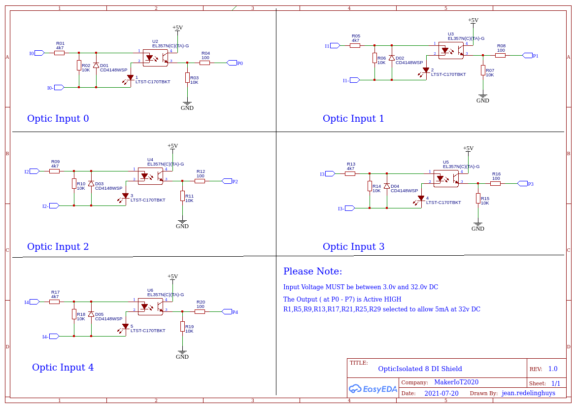
The Circuit Diagram
📷Circuit Diagram, Page 1 of 2
As you can see on page 1, each optically isolated input has a voltage divider resistor network in front of the Opto Coupler. This resistor network also limits the current that can be used by the infrared LED inside of the EL357N chip to 5mA at 32v DC. ( The chip can accept up to 50mA, but it should not be driven so hard ) A diode provides reverse-polarity protection to each input as well.
Another voltage divider on the output side limits the current to the PCF8574 Chip. This can also only source or sink 25mA per IO.
Note that there is NO common ground between the input and output sides of this circuit. That means that you have to provide another ground, usually from your external device… This ensures that galvanic isolation between the two circuits is maintained.
On page 2, we can see the various net connections to the connectors, PCF8574 chip, as well as various jumper headers, to select the interrupt pin [H3] ( For Arduino, D2 or D3, other micro-controllers: you are free to select any GPIO to connect to the D2 or D3 header pin ).
You can also select to enable or disable the pull-up resistors on the I2C bus, by shorting the jumper on [H2].
This is usually only needed on the first shield, or in other words, you need one pair of pullup resistors per i2c bus, not one pair per device!
Device addressing is selected with SW1. 8 addresses are available but switching this switch as per the table on the back of the PCB. It is worth mentioning that depending on the version of the PCF8574 chip that is on the shield, there are 8 addresses available, with 0x20h to 0x27h being common on the PCF8574, and 0x38h to 0x3fh being used on the PCF8574A/T version.
Typical Connection
📷Typical connection of input. Note that there is no common ground between the two devices
The PCB
The shield is built on a double-sided PCB or 71.12mm x 61.72mm. This is only slightly bigger than the standard Arduino Uno. All resistors, capacitors and LED’s are of 0805 sizes. ( smaller than that is a bit hard on my eyes, although it can be done, just takes longer ). A ground plane is provided on both sides of the PCB.
PCB design file
All Arduino pins are broken out on a double row of 2.54mm headers. This allows you to use either the outside row with stack-able male-female headers, like on most shields, or you can use dedicated male and female headers, in a zig-zag pattern to stack the shields.
I have done the same with the ICSP header, as on many other commercially available shields, there is only a single female 3×2 header on the bottom, making it quite annoying to use on another shield.
📷PCB Topside
Circuit diagrams and Schematics
Schematic Diagram, Page 1
Sheet_1.png
Download
Scematic diagram, Page 2
Sheet_2.png
Download


Comments
Please log in or sign up to comment.