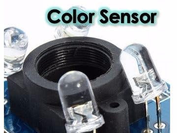
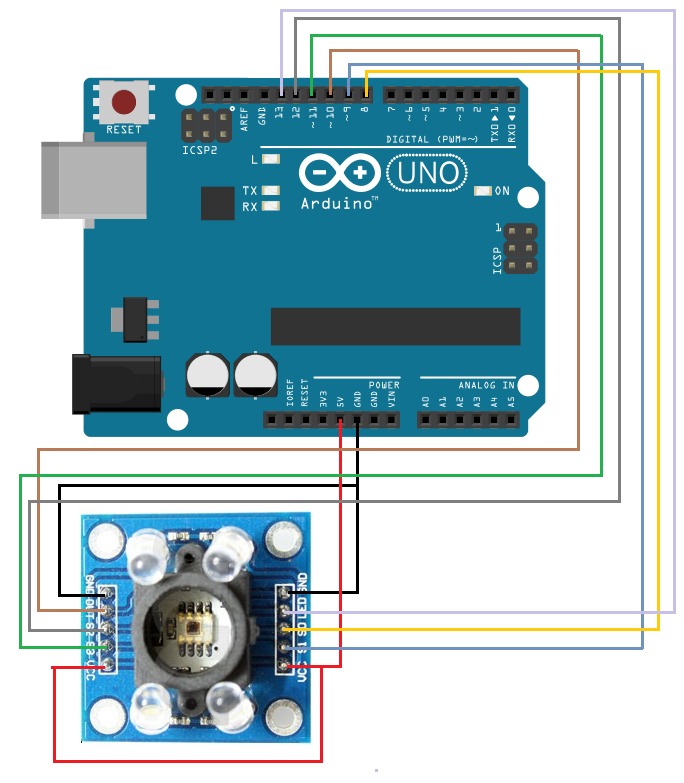
Identification of the sensor: GY-31
Power supply pins:
- 2x GND
- 2x VCC
- 5V
The pins in the control unit:
- S0
- S1
- S2
- S3
- OUT
- LED
The pins in the control unit are used to receive signals that the sensor receives and processes.
- LED - This pin is used for switching on and off the LED. From experience, it is much better to keep the LEDs lighted at all times due to the precision of the sensor in the absence of oscillation.
- OUT - On servant to receive all of the total values of the sensor.
The sensor reads the light reflection through red, green, blue and without filter registers it as data, that is in the program converts the RGB value. We will connect the sensor to the Arduino Uno control unit, of course he supports the whole series of Arduino control units as well as the Raspberry Pi platform.
Declaration and initialization of variables and constants.
The main function setup () are pins s0, s1, s2, s3 and 'OUT' mode is set to OUTPUT.
Pins S0 and S1 with the help of the tool digitalWrite set to HIGH. Why? There are several ways to read the reflection in multiple modes with 2%, 20% and 100% of reflection. Which is best? It depends on the environment and conditions that sensor works. We highly recommend that you try all the modes and choose the one who suits you best for the work.
We made one of our range for red, green and blue color.
Try tasks to make things easier.1. Connect the color sensor with RGB LED and the value read out the sensor must be reflected the color of the LEDs.
2. Oral figure out and explain the term sensor calibration and provide example where it was used with color sensor. I make your color range.


Comments
Please log in or sign up to comment.