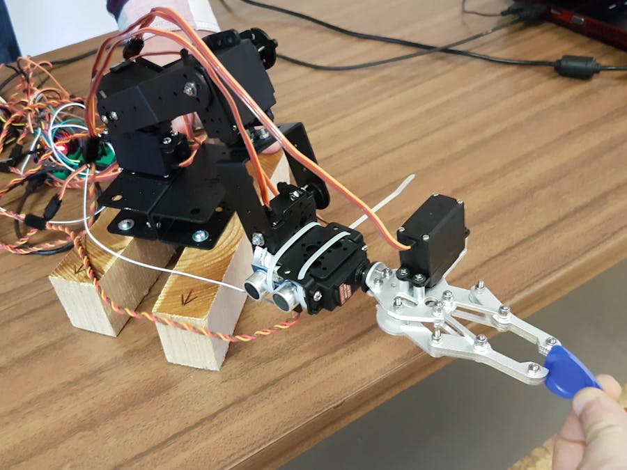
This project consists in programming a robotic arm to move a small object from a point A to a point B with the ability to detect an obstacle between these two positions and to find an alternative path to avoid it, by moving up and down along the Z axis until the object is no longer detected and then fixing the Z position and resuming movement to point B. To achieve this, an ultrasonic sensor was placed on the right side of the extremity of the arm, just below the grip.
The programming was implemented using the concept of Finite State Machines (FSM), which consist of a finite number of states in which the machine can be in at any given time. The advantage of using FSM's is that the time the main loop takes to finish is minimal (milliseconds) and each FSM evaluates the current inputs to generate the right outputs, by doing this, it allows the program to seem asynchronous as it seems to do several tasks at the same time. This allows the robot arm to do diagonal movements (by moving several servos at the same time) or to avoid obstacles while moving without the need to stop the current movement.
These states are linked to each other, which means it needs to transition through the states to do its function. Each state has a specific output and to transition to the next state it needs to verify certain conditions that are associated to that transition. There are cases where the transition to the next state has no conditions, so this transition happens in the next loop cycle. Every machine starts on an initial state and ends the cycle when it reaches that state. This project uses several FSM’s, according to the architecture of the project.
Additionally, interruptions were used for the ultrasonic sensor and for the obstacle. An interruption consists in stopping the program given certain conditions and run a particular piece of code that is associated to it. After running that code, it resumes the program where it stopped. There are two types of interruptions, internal and external. The internal interruptions are basically timers, that activates each time a defined clock cycle has passed. The external interruptions monitor a pin and wait for a certain change on that pin to activate. The change can be of four types, CHANGE(0->1 or 1->0), RISING (0->1), FALLING (1->0) and LOW (0). The FALLING configuration was used to activate the interrupt associated with the ultrasonic sensor, according to the datasheet, by doing this it will save the time of the echo, which happens when the signal of the pin changes from 1 to 0. On the Obstacle FSM the CHANGE configuration was used, due to the need to change a stimulus, which needs to be done each time the signal of the pin changes.
Of the 6 servos, only 5 were used. The servo that wasn’t used is responsible for the rotation of the grip, which wasn’t required for this project.
How to Add Servos to the Current Program (X – represents number of the servo you want to add):
1st Step:- Declaration of the variables of the servo
- Declaration of an additional Global_val
- Example:
int sX =/*servo pin*/;
intservoX_start = /*Starting position in degrees*/;
intFSM_GLOBAL_servoX_VAL;
Servo servoX; //servo X definition
byteFSM_servoX_state = 0;
intFSM_servoX_AP = servoX_start;//to avoid erratic movement
intFSM_servoX_FP = servoX_start;
intFSM_servoX_VAL = 0;
unsignedlong ts_servoX;
- Attaching servo to its corresponding pin in setup
- Assigned starting position to the servo
- Example:
servoX.attach(sX);
servoX.write(servoX_start);
- Add a new Servo FSM for the new servo (copy existing Servo FSM and replace all the existing variables for the ones of the new servo)
- Call the new Servo FSM at the end of the loop
- Example:
FSM_servoX(FSM_servoX_FP,FSM_GLOBAL_servoX_VAL);
- Add new servos positions and Global_val in the states of the Global FSM(add starting position in the first state)
- Example:
FSM_servoX_FP = servoX_start;
FSM_GLOBAL_servoX_VAL = 1;
FSM_servoX_FP= 25;
FSM_GLOBAL_servoX_VAL= 0;
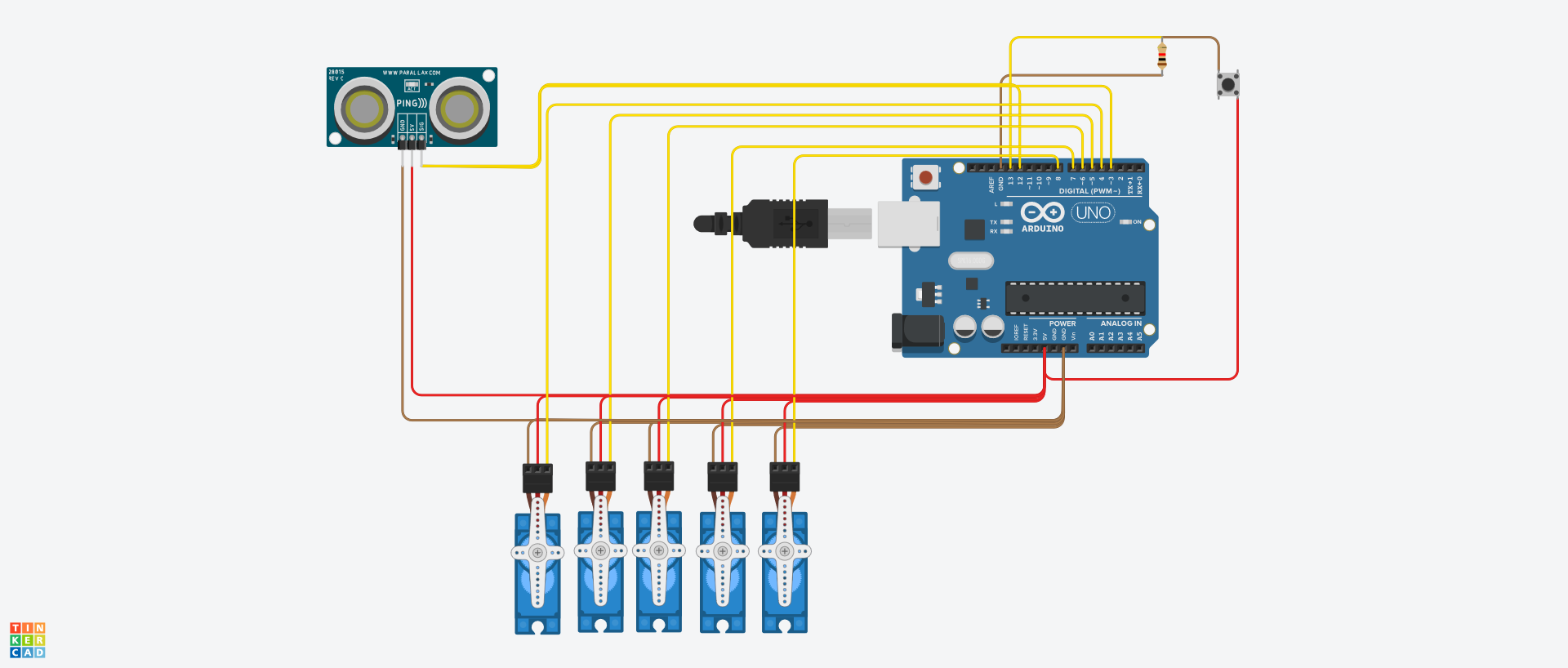
As seen above the entity has two inputs, the ultrasonic sensor and the button, and six outputs that send a pulse to the electronic unit inside each servo which processes the signal and generates the movement of the motor.
ArchitectureThe architecture has nine FSM’s (1 ultrasonic sensor, 1 Obstacle, 1 Global Machine and 1 for each Servo) and two interrupts.
Ultrasonic FSMThe ultrasonic sensor works by emitting a wave (Trigger) and receiving its echo (Echo). Knowing that the wave travels at the speed of sound, the distance of the obstacle can be calculated by measuring the difference of time between the trigger and the echo and multiplying it by the speed of sound. The ultrasonic FSM has 3 states. The first executes the trigger, the second checks if the echo was received. If the echo was received the FSM changes to the next state, if the echo was not received and if a predefined time has passed since the trigger(timeout), the FSM returns to the initial state. The third state calculates the distance, since the trigger and the echo happened within an acceptable amount of time of each other (condition of transition from the second state to the third). The pin of the echo is connected to the interrupt pin, which means that when the sensor receives the echo, the signal of the pin changes and activates the interrupt, which in turn saves the time when the echo was received. This kind of sensor can have interferences or can easily malfunction, which means that it may not receive the echo, making the time of the trigger useless and the calculus of the distance wrong. For this reason, the program checks if a predefined time has passed since the trigger was sent(timeout), and if it has passed the whole cycle restarts. As the distance that the sensor can measure is smaller than 10meters the timeout is defined as 30000 µs, which is approximately 10 meters in distance.
Obstacle FSMThe Obstacle FSM is responsible for generating the stimulus that will activate the interrupt. This happens each time the state changes because the interrupt is on the CHANGE configuration, as stated above. The distance given by the ultrasonic FSM will influence the stimulus to the Obstacle FSM. If the distance is between 2 and 20 cm (obstacle present) it changes the stimulus to 1, which then makes the FSM to change state, changing the signal in the pin of the interrupt, activating it. When the distance is outside the defined interval (no obstacle) it changes the stimulus to 0, which instead makes the FSM to change state, changing the signal in the pin of the interrupt, activating it. Each time this interrupt is activated, it changes the stimulus that goes to the Global FSM, indicating the presence of an obstacle or not. The minimum distance is defined as 2 cm according to the minimum working distance specified on the datasheet.
Global FSMThe Global FSM is responsible for controlling the positions of the robotic arm. To do this it sends the final position(FP) to each servo (each servo has a different FP), in specific states, that represents a specific position of the arm as a whole. To control the state of the Global FSM three main inputs were implemented, the button to initiate the cycle of movement of the arm, the stimulus of the interrupt that makes the FSM exit (obstacle present) or return (no obstacle) to the normal movement, and enter (obstacle present) or exit(no obstacle) the cycle of finding a path to avoid the obstacle, respectively. The third input is a variable of validation of each servo that validates that the servo has reached the given FP (Validates when Servo Val = 1). When all the servos have reached the FP’s then the Global FSM transitions to the next state.
Servo FSMThe Servo FSM moves the servo from one side to the other according to the FP and the actual position(AP), or indicates to the Global FSM that the servo has reached the FP. Additionally, it has a delay in either movement to make sure that the servo has time to physically transition and to avoid extremely fast movements, which might damage the servo.Each servo has its own Servo FSM. When the Global FSM sends a new FP, the Servo FSM checks if AP<FP or if AP>FP and changes to the according state with the corresponding movement (AP + step or AP – step, respectively). The step corresponds to the number of degrees the servos move on each loop cycle. It is defined as 1 degree so that the movement isn’t too fast. When the servo finally reaches the FP (AP = FP), the Servo FSM changes to the state in which the ServoVal = 1. It stays in this state until the Global FSM sends a stimulus (GlobalVal = 1) that allows for the Servo FSM to return to the initial state (ServoVal = 0). This happens to all the servos at the same time. Then it stays in this state until it receives a new FP. The servos have to wait for the GlobalVal because each servo will take a different amount of loop cycles to reach their respective FP, in this way it can be guaranteed that they all have reached the FP and that they all start to move to the next position at the same time.


Comments
Please log in or sign up to comment.