


The ports shown below are PS/2 ports. As we can see there are two PS/2 interfaces for mouse and keyboard.
Gamers who require extremely less latency prefer PS/2 over USB. The PS/2 ports work by sending interrupts to the system, while USB ports works by polling the system continuously. In polling, the processor is always busy. That means the multi-tasking capability of the processor is reduced.
Also in PS/2 if we press down multiple keys of the keyboard it registers all of the key hits. But in USB it doesn't. Some modern software lets us simulate multiple instances of the keyboard at the same time to help register this multi key pressing functionality while using USB plugged keyboard ; but again it is computationally expensive.
Now in any type of serial communication protocol, we have start bit, stop bit, parity bit and error checking bit like CRC (Cyclic Redundancy Check), Checksum, Self correcting hamming code etc.. Now PS/2 mouse protocol is relatively simple and has only start bit check.
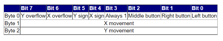
Let's start by implementing the start bit check of the PS/2 mouse protocol. The mouse data packet size is of 3 bytes.
The start bit is the third bit of the first byte. Thus say the 4 bit input ( Byte 0 ) is in. Then by the protocol, the message is received only after in[3] is 1 otherwise the bytes are discarded until appropriate start bit is found. Now let us design a state machine for this. We must remember that the state machine will be non overlapping as we will accept a new message only when the entire previous three byte message is received.
module top_module(
input clk,
input [7:0] in,
input reset,    // Synchronous reset
output done); //
reg [2:0] state,next_state;
parameter BYTE1=0,BYTE2=1,BYTE3=2,DONE=4;
// State transition logic (combinational)
always@(*)begin
case(state)
BYTE1: next_state=(in[3])? BYTE2: BYTE1;
BYTE2: next_state= BYTE3;
BYTE3: next_state= DONE;
DONE:  next_state= (in[3])? BYTE2: BYTE1;
endcase
end
// State flip-flops (sequential)
always@(posedge clk)begin
if(reset)
state<=BYTE1;
else
state<=next_state;
end
// Output logic
assign done =(state==DONE);
endmodule
Now let us add a data-path such that we can output the entire three byte message as soon as the entire message is received.
Most of the state machine logic will remain same
module top_module(
input clk,
input [7:0] in,
input reset,    // Synchronous reset
output [23:0] out_bytes,
output done); //
// FSM that we just built
reg [2:0] state,next_state;
reg [23:0] temp;
parameter BYTE1=0,BYTE2=1,BYTE3=2,DONE=4;
// State transition logic (combinational)
always@(*)begin
case(state)
BYTE1: next_state=(in[3])? BYTE2: BYTE1;
BYTE2: next_state= BYTE3;
BYTE3: next_state= DONE;
DONE:  next_state= (in[3])? BYTE2: BYTE1;
endcase
end
// State flip-flops (sequential)
always@(posedge clk)begin
if(reset)
state<=BYTE1;
else
state<=next_state;
end
always@(posedge clk)begin
case(state)
BYTE1: temp[23:16]=in;
BYTE2: temp[15:8]=in;
BYTE3: temp[7:0]=in;
DONE : temp[23:16]=in;
endcase
end
// Output logic
assign done =(state==DONE);
// New: Datapath to store incoming bytes.
assign out_bytes= temp & {24{done}};
endmodule
Thus we have designed a simple PS/2 mouse controller protocol. So now we will move on to a more complicated serial receiver protocol used by UART and RS232
Complete Serial Receiver for UART and RS232We have seen how to implement start bit in PS/2 mouse protocol. Now, In UART and RS232 the most simplest format of data transmission is start bit, 8 bits of data and stop bit.
Same as the PS/2 protocol, the entire State machine that we have to design will be non overlapping. Now if the stop bit is missed, we have to discard the entire message we had received till that point. We will have to wait for the stop bit and then after receiving a new start bit, we will start getting a new message.
This is the state machine that I designed for this problem. State names are self explanatory. Whenever we are in yay !! 😊 state that means we have received our message. If we are in Stop miss 😢 state that means we have missed our stop bit
module top_module(
input clk,
input in,
input reset,
output done
);
reg [3:0] state,next_state;
parameter start = 4'h0;
parameter data1 = 4'h1;
parameter data2 = 4'h2;
parameter data3= 4'h3;
parameter data4= 4'h4;
parameter data5= 4'h5;
parameter data6= 4'h6;
parameter data7= 4'h7;
parameter data8 = 4'h8;
parameter stopmiss = 4'd9;
parameter faultydone = 4'hA;
parameter stop = 4'hB;
parameter yay = 4'hC;
always@(*)begin
case(state)
start:     next_state=(in)?start:data1;
data1:     next_state=data2;
data2:     next_state=data3;
data3:     next_state=data4;
data4:     next_state=data5;
data5:     next_state=data6;
data6:     next_state=data7;
data7:     next_state=data8;
data8:     next_state=stop;
stop:      next_state=(in)?yay:stopmiss;
yay:       next_state=(in)?start:data1;
stopmiss:  next_state=(in)?faultydone:stopmiss;
faultydone:next_state=(in)?start:data1;
endcase
end
always@(posedge clk)
begin
if(reset)
state<=start;
else
state<=next_state;
end
assign  done= (state==yay);
endmoduleNow as we did with the PS/2 mouse protocol we will add a data path to receive the message once we are in the yay state and validated both start and stop bits. The data path will basically be a 8 bit shift register shifting right at every positive edge of the clock pulse. As soon as done signal becomes one the contents of the shift register is the message received.
module top_module(
input clk,
input in,
input reset,    // Synchronous reset
output [7:0] out_byte,
output done
);
reg [7:0] mayukh;
reg [3:0] state,next_state;
parameter start = 4'h0;
parameter data1 = 4'h1;
parameter data2 = 4'h2;
parameter data3= 4'h3;
parameter data4= 4'h4;
parameter data5= 4'h5;
parameter data6= 4'h6;
parameter data7= 4'h7;
parameter data8 = 4'h8;
parameter stopmiss = 4'd9;
parameter faultydone = 4'hA;
parameter stop = 4'hB;
parameter yay = 4'hC;
always@(*)begin
case(state)
start:     next_state=(in)?start:data1;
data1:     next_state=data2;
data2:     next_state=data3;
data3:     next_state=data4;
data4:     next_state=data5;
data5:     next_state=data6;
data6:     next_state=data7;
data7:     next_state=data8;
data8:     next_state=stop;
stop:      next_state=(in)?yay:stopmiss;
yay:       next_state=(in)?start:data1;
stopmiss:  next_state=(in)?faultydone:stopmiss;
faultydone:next_state=(in)?start:data1;
endcase
end
always@(posedge clk)
begin
if(reset)
state<=start;
else
state<=next_state;
end
assign  done= (state==yay);
always@(posedge clk)begin
if(reset || state==start)
mayukh<=8'h0;
else if(state!=stop)
mayukh<={in,mayukh[7:1]};
end
assign out_byte=mayukh &({8{done}});
endmodule
Now we will impose another check on the serial receiver protocol called parity which is a very common bit used in RS232 and UARTs.
We will be using Odd parity check. Odd Parity means we must make the entire 9 bits of data (8 message bits + 1 parity bit) have odd number of 1s.
Thus the previous state machine should be modified to include the parity checking. State names are self explanatory.
module top_module(
input clk,
input in,
input reset,    // Synchronous reset
output [7:0] out_byte,
output done
);
reg [7:0] mayukh;
reg [3:0] state,next_state;
parameter start = 4'h0;
parameter data1 = 4'h1;
parameter data2 = 4'h2;
parameter data3= 4'h3;
parameter data4= 4'h4;
parameter data5= 4'h5;
parameter data6= 4'h6;
parameter data7= 4'h7;
parameter data8 = 4'h8;
parameter stopmiss = 4'd9;
parameter faultydone = 4'hA;
parameter stop = 4'hB;
parameter yay = 4'hC;
parameter parity =4'hD;
parameter noyay = 4'hE;
parameter parityfault =4'hF;
always@(*)begin
case(state)
start:     next_state=(in)?start:data1;
data1:     next_state=data2;
data2:     next_state=data3;
data3:     next_state=data4;
data4:     next_state=data5;
data5:     next_state=data6;
data6:     next_state=data7;
data7:     next_state=data8;
data8:     next_state=parity;
parity:    next_state=((^mayukh)^in)?stop:parityfault;
parityfault: next_state=(in)?noyay:stopmiss;
stop:      next_state=(in)?yay:stopmiss;
yay:         next_state=(in)?start:data1;
noyay:       next_state=(in)?start:data1;
stopmiss:  next_state=(in)?faultydone:stopmiss;
faultydone:next_state=(in)?start:data1;
endcase
end
always@(posedge clk)
begin
if(reset)
state<=start;
else
state<=next_state;
end
assign  done= (state==yay);
always@(posedge clk)begin
if(reset || state==start)
mayukh<=8'h0;
else if(next_state!=stop &&state!=stop)
mayukh<={in,mayukh[7:1]};
end
assign out_byte=mayukh &({8{done}});
endmodule
Thus we have designed a serial receiver for UART and RS232 using Verilog


_3u05Tpwasz.png?auto=compress%2Cformat&w=40&h=40&fit=fillmax&bg=fff&dpr=2)

Comments