Before DShot the flight control was updating the speed faster than standard PWM rate, this was causing performance and tuning issues. Faster analog PWM was developed, i.e. OneShot125 and several others. For PWM based protocols the receiver must measure the pulse to determine the speed, seldom the transmitter and the receiver have similar clocks accuracy so, there can be some differences, so flight controller software includes a calibration step to find maximum and minimum value.
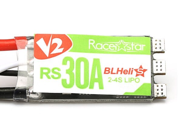
DShot is digital, the speed is encoded into a "packet" along with a telemetry request and check sum, so no need to calibrate. DSHOT supports several speeds 150, 130, 600, and 12000. So, the higher the number the faster the packet bit rate so the faster the packet is sent to the ESC (Electronic Speed Controller)
Here is a basic DSHOT packet:
The packet stream is sent left to right, so speed bit 10, is sent first, then speed bit 9, etc. So, how is a logic 1 and logic 0 encoded? The width determines if the value is a 1 or 0, the longer the width the value is 1. For DSHOT150 here is the table:
DSHOT 150 period of a single bit: 6.67us High Time (1):5.000us High Time (0):2.500us
DSHOT 300 period of a single bit: 3.33us High Time (1):2.500us High Time (0):1.250us
DSHOT 600 period of a single bit: 1.67us High Time (1):1.250us High Time (0):0.620us
DSHOT1200 period of a single bit: 0.83us High Time (1):0.025us High Time (0):0.313us
The PC application will format the 16 bits and the code is in the HTML nwjs application.
DSHOT 150 using FPGAFor this project, receiving telemetry information is not supported, only transmitting DSHOT 16 bit value at 150 rate. The FPGA duty is to send the 16 bit value to the ESC at the programmed clock rate, the value, will be encoded by the PC software, this simplifies the FPGA logic.
This project leverages the Decoding PWM using FPGA project.
The DSHOT150 is implemented in the ip/DSHOT/dshot_out.v:
`default_nettype none
`timescale 1 ns / 1 ns

module dhot_output #(
		parameter update_guardtime = 1000000, //1 second
		parameter clockFrequency = 50000000
	) (
		input  wire        i_clk,          //       clock.clk
		input  wire        i_reset,        //       reset.reset
		input  wire [15:0] i_dshot_value,
		input  wire        i_write,       //            .write
		output wire	       o_pwm
	);


/* state machine state of single bit */
localparam [3:0] INIT_TIME  = 4'h0,
 		HIGH_TIME   = 4'h1,
     	 	LOW_TIME    = 4'h2,
                IDLE_	    = 4'h3;

/* DSHOT Bit time:              (1 - TH1)   (0-T0H)
DSHOT 150 Bit time is 6.67us    5.00us      2.50us
DSHOT 300 Bit time is 3.33us    2.50us      1.25us
DSHOT 600 Bit time is 1.67us    1.25us      0.625us
DSHOT1200 Bit time is 0.83us    0.025       0.313us
*/

/* For DSHOT150 clk is 50Mhz so 0-T0H is  2.50 * 50 = 125
                                0-Off is (6.67 - 2.50us) * 50 = 208.9
*/

localparam [15:0] LOW_HIGH_TIME = 125;
localparam [15:0] LOW_LOW_TIME = 209;

/* For DSHOT150 clk is 50Mhz so 0-T1H is  5.00 * 50 = 250
                                0-Off is (6.67 - 5.00us) * 50 = 83.5
*/

localparam [15:0] HIGH_HIGH_TIME = 250;
localparam [15:0] HIGH_LOW_TIME = 84;To access DSHOT 150, an Avalon slave needs to be created, as before create a slave memory mapped interface, then drag and drop on to system contents and remap the memory addresses. I have included an additional ESC motor controller PWM. Both are shown below:
Here is the new memory map:
Updated fast_serial.v to map the outputs for the motor to pins D2, D3, D4 and D5 of the FPGA. At this time there is no support from the Avalon bus to remap the outputs to be either PWM or DSHOT. The following code is multiplexer hard coded to map either DSHOT or PWM as the output based on a localparam MOTOR_CONTROL.
assign D5 = (MOTOR_CONTROL)?dshot_out_1:pwm_out_1;
assign D4 = (MOTOR_CONTROL)?dshot_out_2:pwm_out_2;
assign D3 = (MOTOR_CONTROL)?dshot_out_3:pwm_out_3;
assign D2 = (MOTOR_CONTROL)?dshot_out_4:pwm_out_4;
To enable either DSHOT150 or OnseShot 125, is to create an Avalon memory mapped address to select ether DSHOT or PWM which then drives the multiplexer. It is also possible to support serial and telemetry using the same method, but using inout.
Here is a screen shot of the new nwjs application, the motor can be driven by channel 0, or with the motor slider. It is recommended that propeller is removed and the motor is securely bolted to a heavy plate.
The Enable Motor button turns on DSHOT generation, so, there will be several beeps from the ESC to notifiy the user that motor is "armed" Increasing the slider will increase the speed. Also, the LED slider is also allows updating the LEDs. Turn on the transmitter and all controls are live.
The serial port interface is slow on recieving data from the FTDI chip because the driver has buffering on transmit, to lower it on Linux:
setserial /dev/<tty_name> low_latencyThe other method is libftdi, there is an API to set the latency_timer, ftdi_set_latency_timer, I made a simple modification to allow the value to be 0. Since the transmit data from the FPGA to the FTDI is 25Mhz, the Avalon packet arrives as one USB packet, but at micro-frame rate.


Comments
Please log in or sign up to comment.