


Hardware components | ||||||
| × | 1 | ||||
 |
| × | 1 | |||
 |
| × | 1 | |||
Software apps and online services | ||||||
 |
| |||||
Hello there engineers and hobbyists! We all love Arduinos, right? But using an Arduino Uno, Nano or any other board for a small task like displaying a simple message on LCD or just fading an LED would be waste of resource and money, so in this video, we will explore a cheap and compact alternative of Arduino called ATtiny85. Let’s get started!
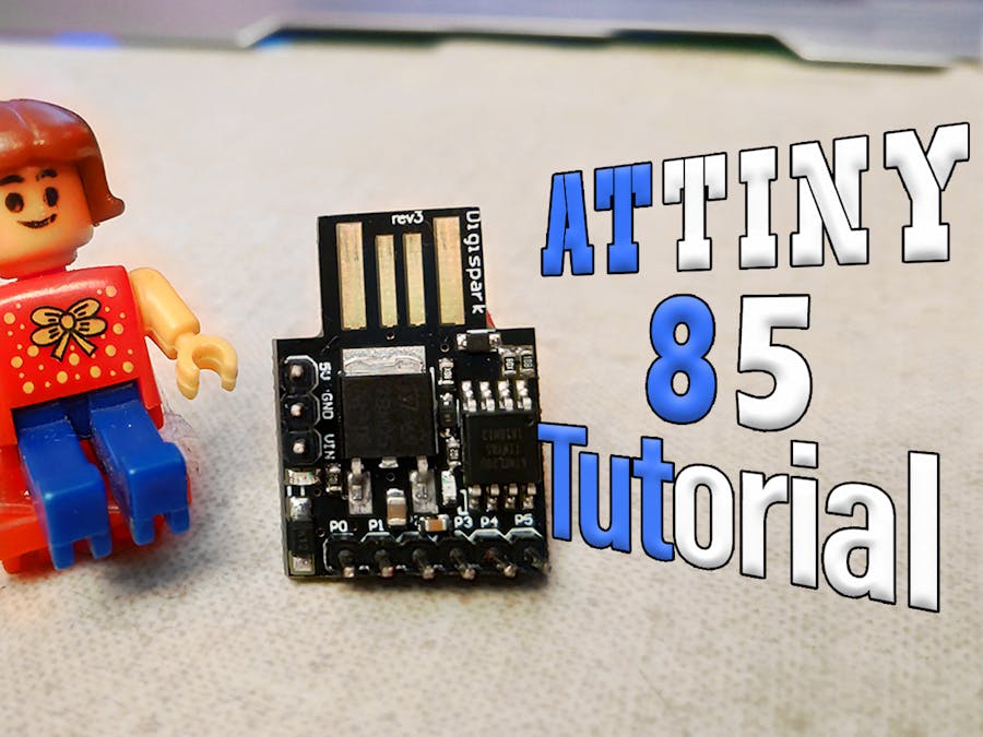
Step 1: Watch the VideoStep 2: Understanding the BoardThe ATtiny85 is similar to Arduino, but it is not Arduino. The ATtiny85 is a micro-controller chip, which has six general purpose IO pins (GPIO), out of which 5 are PWM enabled, and ATtiny85 also supports the SPI and I2C Communication Protocols, but it has only 8Kb of programming memory. So yes, it is not as capable as Arduino board, but it will work just fine for small projects.
Also, this board few other features like:
- Built-in 8 bit timers
- Built-in comparators
- 512 bytes EPROM
- 512 bytes SRAM
Here is a complete data sheet for brief knowledge:
Step 3: Edit Board URLWe need to add boards (DigiStump's ATtiny85) into our Arduino IDE, to do so,
Go to Preference and simply paste the link: https://raw.githubusercontent.com/digistump/arduino-boards-index/master/package_digistump_index.json " on the Additional Board Management URL, then simply press okay and close preferences.
- First open your Arduino IDE,
To install ATtiny board settings in Arduino IDE, select the Contributed type of boards option.
- Go to board manager, under Tools menu.
- Select "DIGISTUMP AVR BOARDS."
- Click on install it!
Now, install the drivers on your computer attached to this step.
- Unzip the attached file.
- Click on DPinst64.exe to install the drivers on your computer.
- Then insert the ATtiny85 board into your computer.
Sometimes your drivers are not installed correctly, in such (unusual) case, we will follow these steps:
- Right click on DigiSpark USB device device and click on Update Device.
- Open Device Manager.
- Click on View Menu and select“Show Hidden option.”
- Click on Device called “LIBUSB-win."
- Browse the drivers from our computer.
- Select the location of drivers stored on computer.
- Now, let’s run a test code to check our ‘ATtiny85’ board. We will simply try blink code, which you can find attached in this step.
<p>/* Blink Code by Akshay Momaya<br> * for Mission Critical Channel
 * ATTINY85 Tutorial for <Mission Critical><mission critical="">
 *  subscribe for more arduino Tuorials and Projects
<a href="https://www.youtube.com/channel/UCM6rbuieQBBLFsxszWA85AQ?sub_confirmation=1">
https://www.youtube.com/channel/UCM6rbuieQBBLFsxs...</a>
 */</mission></p><p>void setup()
 {
  pinMode(1, OUTPUT);
 }</p><p>void loop()
 {
  digitalWrite(1, HIGH);
  delay(1000);
  digitalWrite(1, LOW);
  delay(1000);
 }
</p>
Here, selecting the proper code is the deal breaker of this entire setup. To do so, we will select programmer as “Micronucleus" from Board Menu in Tools.
- Select “Digispark (Deafult-16.5Mhz)” from Board Menu in Tools.
Normally we would compile and upload the code with our Arduino connected, but here in ATtiny85, we will wait for "Micronucleus done. Thank you!" message from compiler. Enjoy!
- Compile the code
- Press UPLOAD button
- wait for plug in device now... (will timeout in 60 seconds) this message.
- Connect the board within 60 seconds .
Ouput of this code will show blinking LED on Pin 1 on the board.
Step 10: Conclusion / Future ScopeWe will do much more projects and Experiments with this board in future, like shrinking your circuit size, making standAlone ATtiny85 projects, etc.
Don’t forget to subscribe to Mission Critical for such awesome tutorials and projects!


Comments
Please log in or sign up to comment.