Mostafa Abcreno
Published © CC BY-NC-SA

LED Matrix Wave Moves With Hand

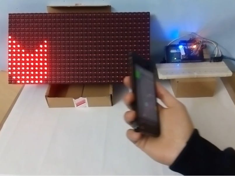
Get into the fantastic world of effects by making a simple design that can move with your hand by using a phone & other simple components.

BeginnerProtip30 minutes9,820
LED Matrix Wave Moves With Hand

Things used in this project

Hardware components

LED Matrix (16 *32)
×1
Arduino Mega 2560
Arduino Mega 2560
×1
1Sheeld
1Sheeld
×1
Android device
Android device
×1
Breadboard (generic)
×1
Male/Male Jumper Wires
×14
5V 2A (2000mA) power supply ( for very high brightness and more than one LED matrix )
×1

Software apps and online services

Arduino IDE
Arduino IDE

Story

Read more

Schematics

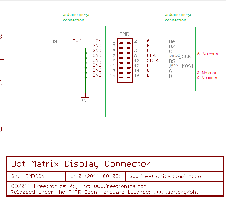
DMD connection

Connect the LED Matrix with Arduino mega

Code

DMD2.cpp

C/C++
Enter to the DMD2 library and change the ( DMD2.cpp) with this one attached, it is only changed to work with mega different pins.
/*
  DMD2 Implementation of SPIDMD, SoftDMD.

 Copyright (C) 2014 Freetronics, Inc. (info <at> freetronics <dot> com)

 Updated by Angus Gratton, based on DMD by Marc Alexander.

---

 This program is free software: you can redistribute it and/or modify it under the terms
 of the version 3 GNU General Public License as published by the Free Software Foundation.

 This program is distributed in the hope that it will be useful, but WITHOUT ANY WARRANTY;
 without even the implied warranty of MERCHANTABILITY or FITNESS FOR A PARTICULAR PURPOSE.
 See the GNU General Public License for more details.

 You should have received a copy of the GNU General Public License along with this program.
 If not, see <http://www.gnu.org/licenses/>.
*/
#include "DMD2.h"

// Port registers are same size as a pointer (16-bit on AVR, 32-bit on ARM)
typedef intptr_t port_reg_t;

SPIDMD::SPIDMD(byte panelsWide, byte panelsHigh)
#ifdef ESP8266
  : BaseDMD(panelsWide, panelsHigh, 15, 16, 12, 0)
#else
  : BaseDMD(panelsWide, panelsHigh, 9, 6, 7, 8)
#endif
{
}

/* Create a DMD display using a custom pinout for all the non-SPI pins (SPI pins set by hardware) */
SPIDMD::SPIDMD(byte panelsWide, byte panelsHigh, byte pin_noe, byte pin_a, byte pin_b, byte pin_sck)
  : BaseDMD(panelsWide, panelsHigh, pin_noe, pin_a, pin_b, pin_sck)
{
}

void SPIDMD::beginNoTimer()
{
  // Configure SPI before initialising the base DMD
  SPI.begin();
  SPI.setBitOrder(MSBFIRST);
  SPI.setDataMode(SPI_MODE0);	// CPOL=0, CPHA=0
#ifdef __AVR__
  SPI.setClockDivider(SPI_CLOCK_DIV4); // 4MHz clock. 8MHz (DIV2 not DIV4) is possible if you have short cables. Longer cables may need DIV8/DIV16.
#elif defined(ESP8266)
  SPI.setFrequency(4000000); // ESP can run at 80mhz or 160mhz, setting frequency directly is easier, set to 4MHz.
#else
  SPI.setClockDivider(20); // 4.2MHz on Due. Same comment as above applies (lower numbers = less divider = faster speeds.)
#endif
  BaseDMD::beginNoTimer();
}

void SPIDMD::writeSPIData(volatile uint8_t *rows[4], const int rowsize)
{
  /* We send out interleaved data for 4 rows at a time */
  for(int i = 0; i < rowsize; i++) {
    SPI.transfer(*(rows[3]++));
    SPI.transfer(*(rows[2]++));
    SPI.transfer(*(rows[1]++));
    SPI.transfer(*(rows[0]++));
  }
}

void BaseDMD::scanDisplay()
{
  if(pin_other_cs >= 0 && digitalRead(pin_other_cs) != HIGH)
    return;
  // Rows are send out in 4 blocks of 4 (interleaved), across all panels

  int rowsize = unified_width_bytes();

  volatile uint8_t *rows[4] = { // Scanning out 4 interleaved rows
    bitmap + (scan_row + 0) * rowsize,
    bitmap + (scan_row + 4) * rowsize,
    bitmap + (scan_row + 8) * rowsize,
    bitmap + (scan_row + 12) * rowsize,
  };

  writeSPIData(rows, rowsize);

  digitalWrite(pin_noe, LOW);
  digitalWrite(pin_sck, HIGH); // Latch DMD shift register output
  digitalWrite(pin_sck, LOW); // (Deliberately left as digitalWrite to ensure decent latching time)

  // Digital outputs A, B are a 2-bit selector output, set from the scan_row variable (loops over 0-3),
  // that determines which set of interleaved rows we are outputting during this pass.
  // BA 0 (00) = 1,5,9,13
  // BA 1 (01) = 2,6,10,14
  // BA 2 (10) = 3,7,11,15
  // BA 3 (11) = 4,8,12,16
  digitalWrite(pin_a, scan_row & 0x01);
  digitalWrite(pin_b, scan_row & 0x02);
  scan_row = (scan_row + 1) % 4;

  // Output enable pin is either fixed on, or PWMed for a variable brightness display
  if(brightness == 255)
    digitalWrite(pin_noe, HIGH);
  else
    analogWrite(pin_noe, brightness);
}

#ifdef ESP8266
// No SoftDMD for ESP8266 for now
#else
SoftDMD::SoftDMD(byte panelsWide, byte panelsHigh)
  : BaseDMD(panelsWide, panelsHigh, 9, 6, 7, 8),
    pin_clk(52),
    pin_r_data(51)
{
}

SoftDMD::SoftDMD(byte panelsWide, byte panelsHigh, byte pin_noe, byte pin_a, byte pin_b, byte pin_sck,
          byte pin_clk, byte pin_r_data)
  : BaseDMD(panelsWide, panelsHigh, pin_noe, pin_a, pin_b, pin_sck),
    pin_clk(pin_clk),
    pin_r_data(pin_r_data)
{
}

void SoftDMD::beginNoTimer()
{
  digitalWrite(pin_clk, LOW);
  pinMode(pin_clk, OUTPUT);

  digitalWrite(pin_r_data, LOW);
  pinMode(pin_r_data, OUTPUT);
  BaseDMD::beginNoTimer();
}


static inline __attribute__((always_inline)) void softSPITransfer(uint8_t data, volatile port_reg_t *data_port, port_reg_t data_mask, volatile port_reg_t *clk_port, port_reg_t clk_mask) {
  // Emulate a single byte SPI transfer using software GPIO. Overall this is actually only marginally slower than normal SPI on AVR.
  //
  // MSB first, data captured on rising edge
  for(uint8_t bit = 0; bit < 8; bit++) {
    if(data & (1<<7))
      *data_port |= data_mask;
    else
      *data_port &= ~data_mask;
    *clk_port |= clk_mask;
    data <<= 1;
    *clk_port &= ~clk_mask;
  }
}

void SoftDMD::writeSPIData(volatile uint8_t *rows[4], const int rowsize)
{
  /* Write out 4 interleaved rows of data using software GPIO rather than SPI. */
  volatile port_reg_t *port_clk = (volatile port_reg_t *)portOutputRegister(digitalPinToPort(pin_clk));
  port_reg_t mask_clk = digitalPinToBitMask(pin_clk);
  volatile port_reg_t *port_r_data = (volatile port_reg_t *) portOutputRegister(digitalPinToPort(pin_r_data));
  port_reg_t mask_r_data = digitalPinToBitMask(pin_r_data);

  for(int i = 0; i < rowsize; i++) {
    softSPITransfer(*(rows[3]++), port_r_data, mask_r_data, port_clk, mask_clk);
    softSPITransfer(*(rows[2]++), port_r_data, mask_r_data, port_clk, mask_clk);
    softSPITransfer(*(rows[1]++), port_r_data, mask_r_data, port_clk, mask_clk);
    softSPITransfer(*(rows[0]++), port_r_data, mask_r_data, port_clk, mask_clk);
  }
}
#endif

BaseDMD::BaseDMD(byte panelsWide, byte panelsHigh, byte pin_noe, byte pin_a, byte pin_b, byte pin_sck)
  :
  DMDFrame(panelsWide*PANEL_WIDTH, panelsHigh*PANEL_HEIGHT),
  scan_row(0),
  pin_noe(pin_noe),
  pin_a(pin_a),
  pin_b(pin_b),
  pin_sck(pin_sck),
#ifdef ESP8266
  default_pins(pin_noe == 15 && pin_a == 16 && pin_b == 12 && pin_sck == 0),
#else
  default_pins(pin_noe == 9 && pin_a == 6 && pin_b == 7 && pin_sck == 8),
#endif
  pin_other_cs(-1),
  brightness(255)
{
}

void BaseDMD::beginNoTimer()
{
  digitalWrite(pin_noe, LOW);
  pinMode(pin_noe, OUTPUT);

  digitalWrite(pin_a, LOW);
  pinMode(pin_a, OUTPUT);

  digitalWrite(pin_b, LOW);
  pinMode(pin_b, OUTPUT);

  digitalWrite(pin_sck, LOW);
  pinMode(pin_sck, OUTPUT);

  clearScreen();
  scanDisplay();
}

moved_sea.ino

Arduino
After connecting we are ready to use the code so connect Arduino to your computer and upload the code in the attached code file.
/* Include 1Sheeld library. */
#include <OneSheeld.h>
#define CUSTOM_SETTINGS
#define INCLUDE_ACCELEROMETER_SENSOR_SHIELD
/* Include LED Matrix library. */
#include <SPI.h>
#include <DMD2.h>

SoftDMD dmd(1, 1); // DMD controls the entire display


float Read;
//                                            //
// Values of columns for each horizontal wave //
//                                            //
int Sy1[] = {5, 6, 7, 8, 9, 9, 8, 7, 6, 5, 5, 6, 7, 8, 9, 9, 8, 7, 6, 5, 5, 6, 7, 8, 9, 9, 8, 7, 6, 5, 6, 7};
int Sy2[] = {6, 7, 8, 9, 10, 10, 9, 8, 7, 6, 6, 7, 8, 9, 10, 10, 9, 8, 7, 6, 6, 7, 8, 9, 10, 10, 9, 8, 7, 6, 7, 8};
int Sy3[] = {7, 8, 9, 10, 11, 11, 10, 9, 8, 7, 7, 8, 9, 10, 11, 11, 10, 9, 8, 7, 7, 8, 9, 10, 11, 11, 10, 9, 8, 7, 8, 9};
int Sy4[] = {8, 9, 10, 11, 12, 12, 11, 10, 9, 8, 8, 9, 10, 11, 12, 12, 11, 10, 9, 8, 8, 9, 10, 11, 12, 12, 11, 10, 9, 8, 9, 10};
int Sy5[] = {9, 10, 11, 12, 13, 13, 12, 11, 10, 9, 9, 10, 11, 12, 13, 13, 12, 11, 10, 9, 9, 10, 11, 12, 13, 13, 12, 11, 10, 9, 10, 11};
int Sy6[] = {10, 11, 12, 13, 14, 14, 13, 12, 11, 10, 10, 11, 12, 13, 14, 14, 13, 12, 11, 10, 10, 11, 12, 13, 14, 14, 13, 12, 11, 10, 11, 12};
int Sy7[] = {11, 12, 13, 14, 15, 15, 14, 13, 12, 11, 11, 12, 13, 14, 15, 15, 14, 13, 12, 11, 11, 12, 13, 14, 15, 15, 14, 13, 12, 11, 12, 13};
int Sy8[] = {12, 13, 14, 15, 16, 16, 15, 14, 13, 12, 12, 13, 14, 15, 16, 16, 15, 14, 13, 12, 12, 13, 14, 15, 16, 16, 15, 14, 13, 12, 13, 14};
int Sy9[] = {13, 14, 15, 16, 17, 17, 16, 15, 14, 13, 13, 14, 15, 16, 17, 17, 16, 15, 14, 13, 13, 14, 15, 16, 17, 17, 16, 15, 14, 13, 14, 15};

int i = 0; // counter for clumns values at ON state
int X = 0; //counter for rows values at ON state
int j1 = 0; //counter for clumns values at Off state
int j2 = 0; //counter for clumns values at Off state
int B = 2; // for separate between waves to can be seen by 4 leds
int C = 3; // for separate between waves to can be seen by 3 leds
int ip = 31; // counter for clumns values at ON state but in other direction of motion
int Xp = 31; // counter for rows values at ON state but in other direction of motion
int j1p = 31; // counter for clumns values at OFF state but in other direction of motion
int j2p = 31; //// counter for clumns values at OFF state but in other direction of motion
int Bp = 29; // for separate between waves to can be seen by 4 leds
int Cp = 28; // for separate between waves to can be seen by 3 leds
void setup()
{
  /* Start 1sheeld communication. */
  OneSheeld.begin();
  dmd.setBrightness(10); // set brightness
  dmd.begin();


}
/*--------------------------------------------------------------------------------------
  loop
  Arduino architecture main loop
--------------------------------------------------------------------------------------*/
void loop(void)
{
  Read =  AccelerometerSensor.getX();// read the value of accelerometer of your phone sensor
  if (Read < -4) // mobile go right
  {
    // draw the hoizontal waves
    dmd.setPixel(X, Sy1[i], GRAPHICS_ON);
    dmd.setPixel(X, Sy2[i], GRAPHICS_ON);
    dmd.setPixel(X, Sy3[i], GRAPHICS_ON);
    dmd.setPixel(X, Sy4[i], GRAPHICS_ON);
    dmd.setPixel(X, Sy5[i], GRAPHICS_ON);
    dmd.setPixel(X, Sy6[i], GRAPHICS_ON);
    dmd.setPixel(X, Sy7[i], GRAPHICS_ON);
    dmd.setPixel(X, Sy8[i], GRAPHICS_ON);
    dmd.setPixel(X, Sy9[i], GRAPHICS_ON);
    X = X + 1;
    i = i + 1;
    delay(50);
    // draw off  to make continuous motion
    dmd.setPixel(B , Sy1[j1], GRAPHICS_OFF);
    dmd.setPixel(C , Sy2[j2], GRAPHICS_OFF);
    dmd.setPixel(B , Sy3[j1], GRAPHICS_OFF);
    dmd.setPixel(C , Sy4[j2], GRAPHICS_OFF);
    dmd.setPixel(B , Sy5[j1], GRAPHICS_OFF);
    dmd.setPixel(C , Sy6[j2], GRAPHICS_OFF);
    dmd.setPixel(C , Sy7[j1], GRAPHICS_OFF);
    dmd.setPixel(C , Sy8[j2], GRAPHICS_OFF);
    dmd.setPixel(C , Sy9[j1], GRAPHICS_OFF);
    B = B + 1;
    C = C + 1;
    j1 = j1 + 1;
    j2 = j2 + 1;
    if ( X > 31) // the final horizontal LED has been lightened
    { X = 0; // back to the first one
      i = 0; // and first value of clumn
    }
    if ( B > 31 ) // the final horizontal LED has been turned oFF
    { B = 0; // back to restart the cycle
      j1 = 0; // and first value of clumn 
    }
    if ( C > 31 ) // the final horizontal LED for ((mixed waves)) has been turned oFF
    { C = 0; // back to restart the cycle
      j2 = 0; //// and first value of clumn
    }
  }

  //                                                   //
  // the same but in the opposite direction of motion //
  //                                                  //
  else if (Read > 4 ) // mobile go left
  {
    dmd.setPixel(Xp, Sy1[ip], GRAPHICS_ON);
    dmd.setPixel(Xp, Sy2[ip], GRAPHICS_ON);
    dmd.setPixel(Xp, Sy3[ip], GRAPHICS_ON);
    dmd.setPixel(Xp, Sy4[ip], GRAPHICS_ON);
    dmd.setPixel(Xp, Sy5[ip], GRAPHICS_ON);
    dmd.setPixel(Xp, Sy6[ip], GRAPHICS_ON);
    dmd.setPixel(Xp, Sy7[ip], GRAPHICS_ON);
    dmd.setPixel(Xp, Sy8[ip], GRAPHICS_ON);
    dmd.setPixel(Xp, Sy9[ip], GRAPHICS_ON);
    Xp = Xp - 1;
    ip = ip - 1;
    delay(50);
    dmd.setPixel(Bp , Sy1[j1p], GRAPHICS_OFF);
    dmd.setPixel(Cp , Sy2[j2p], GRAPHICS_OFF);
    dmd.setPixel(Bp , Sy3[j1p], GRAPHICS_OFF);
    dmd.setPixel(Cp , Sy4[j2p], GRAPHICS_OFF);
    dmd.setPixel(Bp , Sy5[j1p], GRAPHICS_OFF);
    dmd.setPixel(Cp , Sy6[j2p], GRAPHICS_OFF);
    dmd.setPixel(Bp , Sy7[j1p], GRAPHICS_OFF);
    dmd.setPixel(Cp , Sy8[j2p], GRAPHICS_OFF);
    dmd.setPixel(Bp , Sy9[j1p], GRAPHICS_OFF);
    Bp = Bp - 1;
    Cp = Cp - 1;
    j1p = j1p - 1;
    j2p = j2p - 1;
    if ( Xp < 0)
    { Xp = 31;
      ip = 31;
    }
    if ( Bp < 0 )
    { Bp = 31;
      j1p = 31;
    }
    if ( Cp < 0 )
    { Cp = 31;
      j2p = 31;
    }
  }
}

Credits

Mostafa Abcreno

Mostafa Abcreno

2 projects • 3 followers

Comments