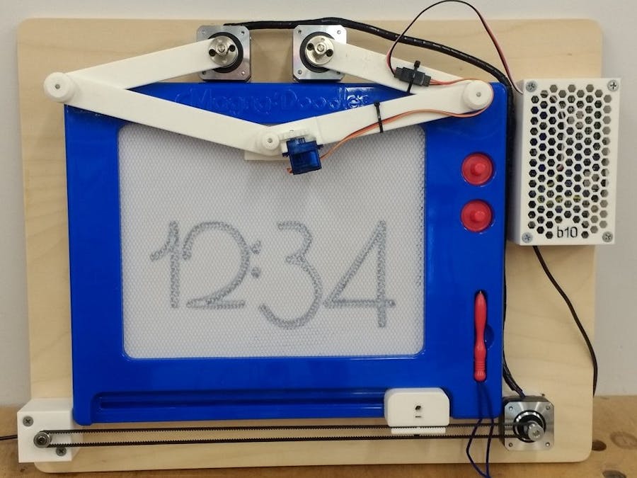
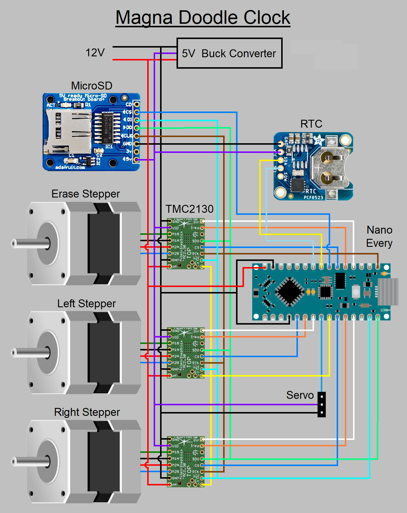
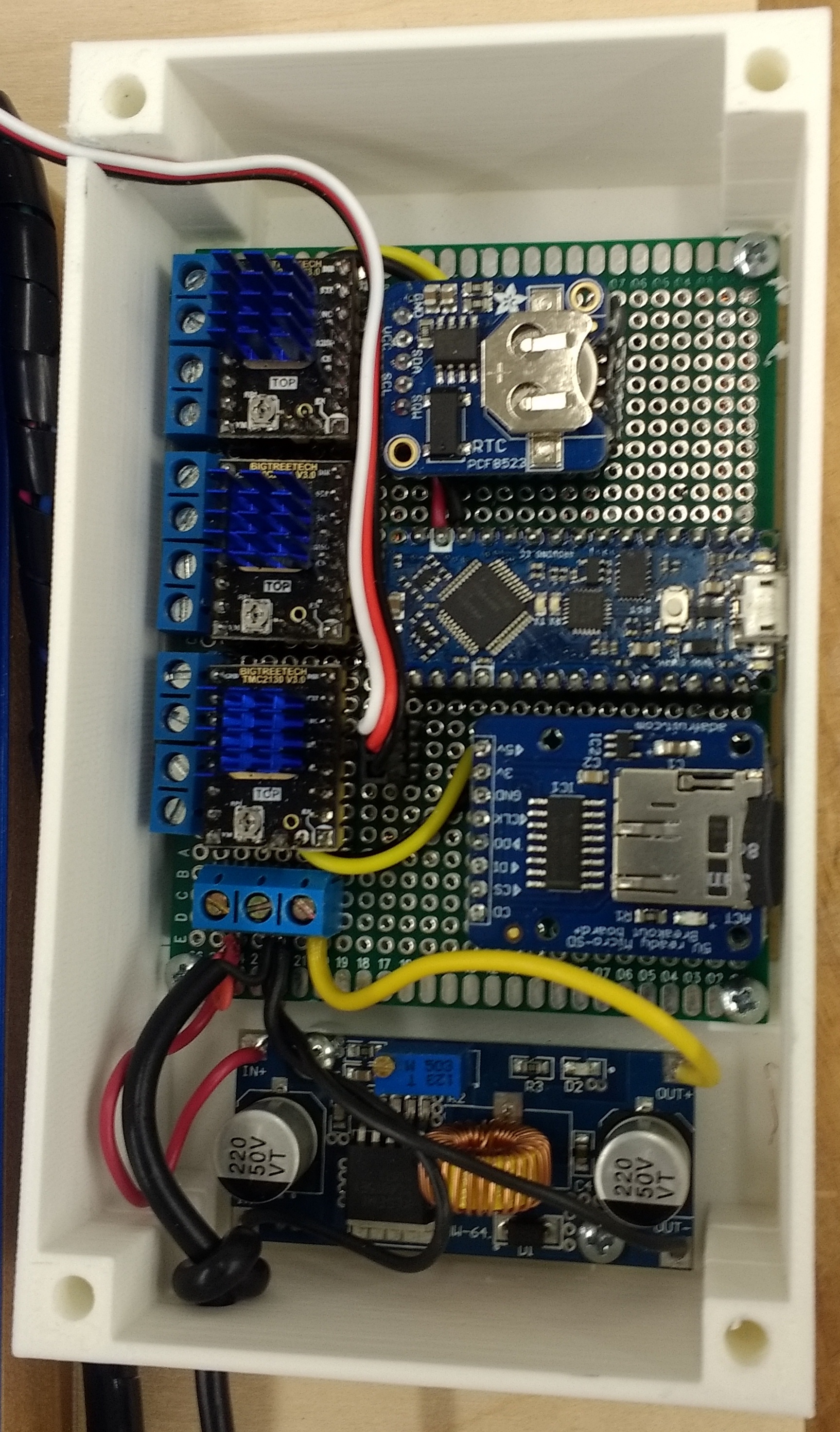
I have a thing for clocks. This is my 4th clock design (and the only one that works at the moment, lol). I wanted to do something similar to my Etch a Sketch and thought a clock made from a Magna Doodle would be fun. A quick search found these existing projects online: RoboClock, DoodleClock, and the famous PlotClock. But, as usual, I wanted to try making my own version.
DISCLAIMER!!!- There is no warranty expressed / implied with this free software.
- Do not leave this plugged in or unattended. Stepper motors can get very hot if not setup properly and may start a fire. This is meant as a novelty item, not as your primary clock.
- It is not my responsibility if it doesn't keep the correct time, makes fun of your mother, or burns your house down.
- Do not use this program for commercial / resale use.
The back frame is made from 1/2" baltic birch plywood. Make a "picture frame" out of 3/4" poplar to space the Magna Doodle out from the plywood. Cut slots for the stepper motor so you can tension the eraser belt. Open up the Magna Doodle and screw the back to the "picture frame". Drill holes thru everything so you can reassemble the front of the Magna Doodle from the back of the frame.
The mechanism that holds the slider to the magnet bar is fairly sloppy. So, I made a "square" that you can glue on to make things a bit more rigid. Also, check if there is a gap between the bar magnet and the back of the screen. You can shim out the magnet in spots to get a clean erase.
I made the 3D printed parts from PLA, 20% gyroid infill, 4 layers on top / bottom, and 4 perimeters. But, your normal material and settings you use should work fine. Everything should print well, except for the rack (which needs supports). It came out so rough on mine that I pushed it on a piece of 1/8" rod and smoothed it out on the lathe.
Stepper Motors:I originally designed this around short body NEMA 17 stepper motors, but the two top units didn't have enough torque and got very hot. So, I went with the longer ones (40mm). Because of the change, I had to bump out the Magna Doodle by 3/4" due to the way I am mounting everything. I am still using a short body stepper motor for the eraser, but the longer one will work better.
Homing:Unlike servos, the stepper motors need a way to set a startup position. My original plan was to use "sensorless homing" with the TMC2130 drivers, but I couldn't get it to work the way I wanted. You may notice that when you power up the stepper motors, they will "jump" to a new position. These are the main coils aligning everything before the microsteps kick in. We can use one of these positions as a home. Find a position near the top of the screen (but not touching the top). Hold everything in place and glue the cradle to the screen with hot glue. Change the #defines HOME_X and HOME_Y in the code to match this new location. You can measure it, but I found it is best to draw a large rectangle and tweak the values until everything is straight (see sub DrawRect).
SCARA:The SCARA design is known as a "5 bar parallel arm". The arms only use two sizes of the brass tubing for the joints: The one with a 1/8" inside diameter and the next size up.
For the two middle joints: Glue a 0.35" long piece of the smaller tube into both of the bottom arms. Press a 7/8" long piece of 1/8" drill rod into top arms, slide on the bottom arm, and press on a cap. The outer pieces should be tight on the drill rod and the middle should be free to spin.
For the bottom joint (pen): Glue a 0.35" long piece of the larger tube into the right bottom arm. Press or glue a 1-1/4" piece of the smaller tube into the left bottom arm. The small tube should extend almost to the drawing surface and up to the thin cap. Drill out a cap to fit the smaller tube and put underneath the left arm. Slide on the right bottom arm and press on the thin cap. I used a 5/8" diameter x 3/8" thick piece of UHMW plastic on the bottom of this joint to slide on the screen without scratching. See picture under Magnet section.
Fonts:I wanted to use a better looking font with the design. At first, I was looking at Hershey fonts, but wanted more variety. I found that TrueType fonts are just made from lines and quadratic Bezier curves that I can make in the program.
Almost any TrueType font should work, but here are some tips for choosing them:
- Don't use an Italic font or one where the characters intrude in the space of others. Each character of the font should be contained in its own rectangle. If not, the eraser will wipe away part of the previous digit.
- Use a font with a little space between the characters. Same issue as above.
- Don't use complicated fonts. The program has to store all of the points of each "contour" in an array. I have it set to hold 100 points, but you can increase this number. If it doesn't draw anything, this may be the reason.
I have included several free fonts in the zip file. Just save the numbered directories to a SD card that is formatted in FAT16 or FAT32. Here is how to add your own fonts:
- Install python: Download Python | Python.org
- Install FontTools for python: fonttools · PyPI
- Find / download your favorite TrueType font into a empty directory. I didn't have any luck with Open Type fonts (otf). Google Fonts and Font Squirrel are good places to find free fonts.
- Open a command prompt to the directory where your font is saved. Run the command "ttx -g myfontname.ttf". This will extract the binary ttf file into a lot of XML text files.
- Find the glyph files for 0 thru 9 and rename them to only include the name (ex: zero.ttx, one.ttx, two.ttx. Do the same for the colon and hmtx files. Look at the included directories for examples. Delete all other files.
- Save these files into a new directory on the SD card. The directories must be sequential numbers starting with 1.
- Update the "#define" for NUM_FONTS in the code and upload to the Arduino.
The RTC I bought is not very accurate. If you want a more precise device, try the Adafruit DS3231. To set the time, use the example included with the Adafruit RTC library.
Magnet:My original plan was to use an electromagnet to draw the time. I extended the end pivot shaft and wound on some magnet wire. It worked, but got very hot and the image was faint (the RoboClock design uses a similar method and is also faint). So, I went with a 9g servo and designed a gear and rack system. Put a 3mm x 1mm magnet on the end of a short piece of 1/8" drill rod and glue on the rack. You can try a 2mm magnet to make a thinner line. When drawing, the magnet should be slightly retracted so it isn't always rubbing on the screen. There is a "#define" in the code that will let you set the distance.


Comments
Please log in or sign up to comment.