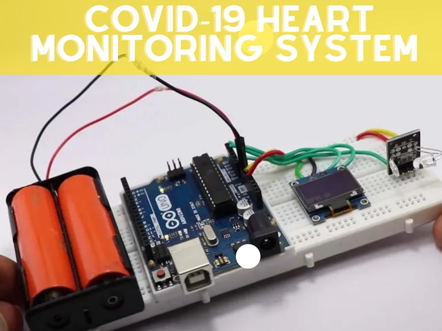
The Heart monitoring system is the most common management system to detect heart attacks and expected heart failure, before the ECG monitoring system. In this project, I will describe the development of an effective heart monitoring system with the help of Arduino, OLED, and pulse sensors.
If you are planning to develop a project that solves a particular problem that this project is specified for you. Currently, the heart monitoring system is too expensive, while the Covid-19 increases it demand therefore it has become difficult for the common man to buy such a type of system.
This post instructs you to develop a heart monitoring system step by step with the help of a circuit diagram and code with instructions, so you don't need to go anywhere else for its development.
What exactly the Arduino Plus monitor is?
This project is a plug-and-play device that can accurately monitor the heartbeat of the person instantly whenever someone places their finger on the sensor.
What is Arduino pulse Rate Monitor?This is a USB-powered or plug-and-play device that can show the rate of heartbeat very instantly as soon as the fingers are placed on the sensor.
This project isn't much expensive to build and anyone with basic experience of Arduino can easily build and develop this project.
How Does Pulse Rate Monitor WorksThe basic principle of the working of the heart plus monitoring system depends upon the working of the pulse sensor.
This tiny sensor is the pulse monitoring sensor as shown in the picture above, there are various types of sensors that monitor different accuracy levels.
We selected this sensor for the monitoring of pulse but if you got an infrared type that will be great. The working of this sensor is quite simple. This sensor has an infrared LED transmitter and the receiver with bulbs embedded on the ( Printed Circuit Board ) PCB. When someplace a finger on the sensor the infrared lights form the sensor and it hit the blood vessels of the and then later travels to the receivers. These values will and changes converted into BPM with the help of coding.
The code and the circuit diagram of the project are also shown in the figure below, in the circuit diagram shows the battery to power the project can be added to Vcc pins of the Arduino. Additionally, the person can also add a USB for powering up the circuit.
Wiring OLED DisplayThe OLED display usually has 4 pins output and input pins i.e Vcc, Scl, Sca, and Gnd. The Gnd and Vcc are for the powerup like positive and negative charges will be connected to the breadboards selected for the Ground and Vcc. Whereas the other two Scl or serial clocks will be attached to the A5 pins of Uno and Sda or serial data to A4 pin of Uno.
Connections fo the Pulse Sensor
The pulse sensor has 3 is are of two pins 3 pins, while 2 for positive and negative, and the remaining pins are known to be the single pin that should be connected to analog as defined in the code. Here in this project, we defined A0 for signaling of the pulse sensor. If you are using External batteries you can connect them to Vin and GND pin of Uno. Also, it is important to upload the complete code to Uno. You can download the OLED Library from here and also code from here
How to use it?In order to use this project, you should avoid direct light source interference with the sensor that might give you inaccurate values.
Connect the power supply to the circuit with the help of a USB or batteries. Then palace your finger on the sensor and wait. After some time you will get the BPM
You can compare it with your smartwatch or actual measuring device for accuracy.
Here is a link to my website https://aquabcasing.com/


_6DpcGprDoK.jpg)


_3u05Tpwasz.png?auto=compress%2Cformat&w=40&h=40&fit=fillmax&bg=fff&dpr=2)
Comments
Please log in or sign up to comment.