Meet Tillu - The Robot, a unique fusion of advanced robotics and creativity designed to inspire learning and innovation! Powered by the UNIHIKER running Debian OS. Tillu leverages the capabilities of a robust control system to deliver lifelike movements and dynamic interactions. At the core of its design are 15Kg servo motor legs, enabling it to walk, dance, and perform complex movements with precision.
Tillu’s expressive personality comes alive with a variety of facial expressions displayed on its built-in screen, alongside a rich suite of sensors, including:
- A microphone for voice recognition.
- A 6-axis gyroscope for balance and orientation.
- A buzzer for sound-based interactions.
- And a display that adds an extra dimension of charm!
This robot is not just about functionality; it's a platform for creative possibilities. Whether you're programming its movements using Python or exploring visual programming with Mind+, Tillu is the perfect companion for learners and enthusiasts alike.
Designed with InnovationInspired by the beloved Otto DIY robots, Tillu's design journey involved extensive work in Fusion 360 for CAD modeling and precise 3D printing to bring it to life. Every detail, from its sturdy servo-driven legs to its modular design, is tailored for durability and aesthetics.
Endless PossibilitiesWith example codes already developed, Tillu can:
- Move in any direction: forward, backward, left turn, right turn.
- Express emotions with diverse facial expressions.
- Perform 10+ unique dance steps, making it the life of the party!
- Respond to voice commands through its advanced speech recognition system.
Building Tillu is not just a project; it's a learning experience. Dive deep into robotics, explore the intricacies of programming, and unleash your creativity by customizing its movements and expressions. Whether you’re a student, hobbyist, or maker, Tillu is a steppingstone into the exciting world of robotics.
Let’s bring Tillu to life and push the boundaries of what robots can do!
Sponsored by JLCMC: Your Go-To Partner for Mechanical Parts!Introducing JLCMC, the newest addition to the trusted JLC family, delivering high-quality mechanical parts at the best prices in the market. With a legacy of excellence established by JLCPCB, JLCMC is here to provide reliable and affordable solutions for all your mechanical needs.
Why Choose JLCMC?
- A Trusted Name:
- JLCMC is built on the foundation of JLC services, a global leader in PCB manufacturing and prototyping. Their commitment to quality and customer satisfaction carries forward into their mechanical parts services.
- Unbeatable Prices:
- True to the JLC legacy, JLCMC offers mechanical parts at industry-leading prices, ensuring that your projects stay on budget without compromising on quality.
- Wide Range of Products:
- From precision-engineered components to custom solutions, JLCMC has everything you need to bring your ideas to life, whether you're a hobbyist or a professional.
- Global Trust:
- JLC services have earned the trust of millions of makers worldwide. With JLCMC, you get the same reliability, now in the realm of mechanical parts.
Check Out This Offers and Customized solutions from JLCMC:
Visit JLCMC.com to explore their offerings, claim your $19 coupons for the new user registration, and take advantage of the amazing year-end discounts. Join the growing community of makers and professionals who trust JLCMC for their mechanical needs.
Supplies1x Unihiker
4x Servo
1x Touch Sensor
Tools:
Step 1: CAD & 3D PrintingTo bring Tillu to life, I started by designing the robot in Fusion 360, a versatile CAD software. Here’s a breakdown of the design process:
Design Overview
- Component Import: I imported all the standard components like the UNIHIKER, servo motors, and manually measured dimensions to create the battery manager board.
- Robot Body Design:
- Housing (Head): Designed to hold the heavy battery and UNIHIKER securely.
- Main Body (Center Frame): Acts as the structural backbone, connecting the head and legs while ensuring stability.
- Cover Panel: Enhances the aesthetics of the robot.
- Legs and Feet: Inspired by Otto DIY robots for smooth movement and balance.
- Headphone Design: Added for a fun, cool look, giving Tillu extra personality!
- Screwing Mechanism: The design incorporates a screwing mechanism for easy assembly.
- Accessibility: The back of the housing features slots for the power button and two USB Type-C ports—one for charging the battery and another for programming the UNIHIKER.
Modifications and Downloads
You can open the model in Fusion 360 to modify it as per your requirements. Alternatively, you can directly download the STL files for 3D printing.
3D Printing Requirements
Below is a list of parts to print:
1x Housing.stl
1x Main.stl
1x Visor.stl
1x Cover.stl
1x Servo Housing Right.stl
1x Servo Cover Right.stl
1x Servo Housing Left.stl
1x Servo Cover Left.stl
1x Right Leg.stl
1x Left Leg.stl
1x Head Phone P1.stl
1x Head Phone P2.stl
2x Head Phone P3.stl
Visit Maker World for downloading the 3D Printer files
Color Scheme: I used dark gray and orange filament to give Tillu a sleek dual-colored look.
Once all the 3D-printed parts are ready, it's time to assemble them. Some parts are designed to be printed in multiple pieces to minimize unwanted supports during 3D printing. Here's how you can assemble them step by step:
Assembling the Housing and Visor
Parts Needed:
- Housing.stl (Gray)
- Visor.stl (Orange)
Steps:
- Take the Housing (Head) part and locate the slot for the visor.
- Insert the Visor into its slot in the housing.
- Use a small amount of quick glue to secure the visor in place. Be careful to avoid excess glue for a clean finish.
The visor design adds an aesthetic dual-color line to the robot's face, giving it a distinctive personality.
Assembling the Headphones
Parts Needed:
- Head Phone P1.stl
- Head Phone P2.stl
- Head Phone P3.stl (2 pieces)
Steps:
- Dual-Color Printing: If you want a dual-color look for the headphone parts, use the filament change technique. Pause the print mid-way and switch filaments to achieve the desired effect.
- Once printed, align the four headphone parts:
- Attach Head Phone P2 to Head Phone P1.
- Attach both Head Phone P3 pieces to complete the headphone design.
- Although the parts are designed as snug fits, you can apply a small amount of glue if needed for extra durability.
Assembly Notes:
Ensure you handle the parts carefully to avoid smudging glue on the outer surfaces.
Allow the glue to dry completely before moving on to the next step.
Step 3: Adding Connectors to Servo MotorsThe servo motors come with their own connectors, but unfortunately, these are not compatible with the Unihiker’s connector pins. Therefore, we need to modify the connectors to ensure proper compatibility and connectivity.
Understanding the Connections
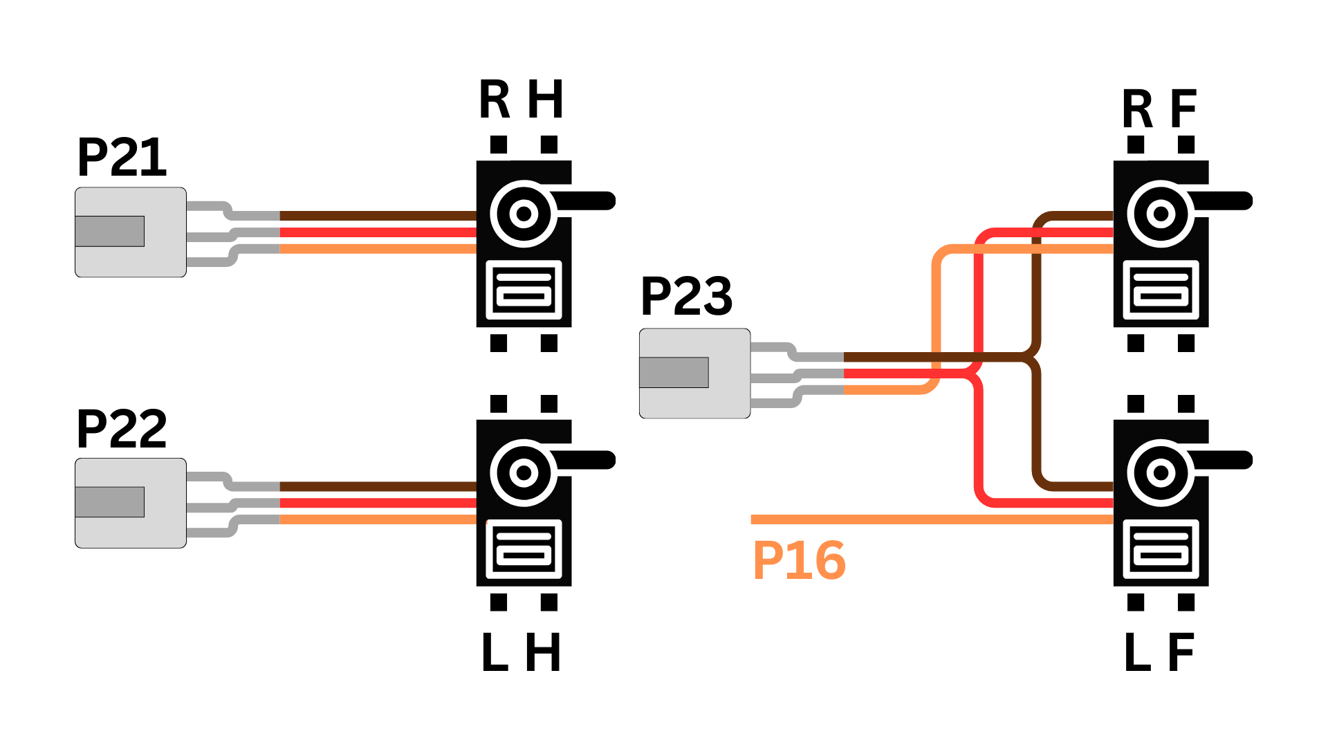
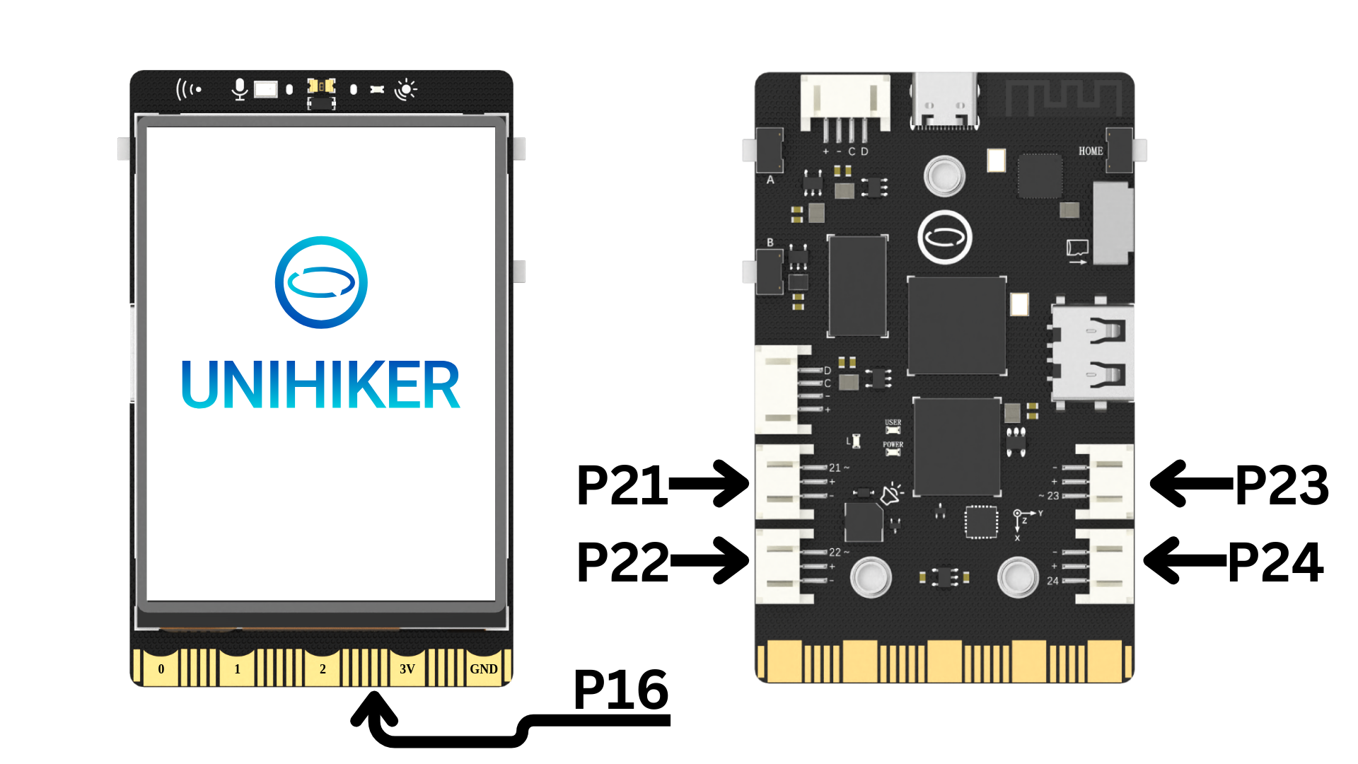
- The Unihiker board has three GPIO connectors (P21, P22, and P23) with PWM signals, but we need to connect four servo motors.
- To address this:
- We’ll use the available GPIO pins for the first three motors.
- The signal pin for the fourth motor will be soldered directly to P16 on the board.
Steps to Modify and Add Connectors
Preparing the Connectors:
- Take the two dual-sided three pin connectors that come with the Unihiker board.
- Cut them in half, creating four separate connectors.
- Reserve three connectors for the servo motors and one for the touch sensor (used in a later step).
Connecting the Servo Motors:
- Use two connectors to connect two servo motors separately. Follow the polarity and wiring diagram as shown in the image:
- Signal (Orange)
- 5V (Red)
- GND (Brown)
- Make sure the orientation of the connectors matches the diagram.
Connecting Two Servos to One Connector:
- For the third connector:
- Connect the GND and 5V wires of both servos to the same connector.
- Route the signal wire of one servo to the connector.
- Leave the signal wire of the second servo open; this will later be soldered to P16.
Verify all connections for correct polarity and alignment with the provided wiring diagram.
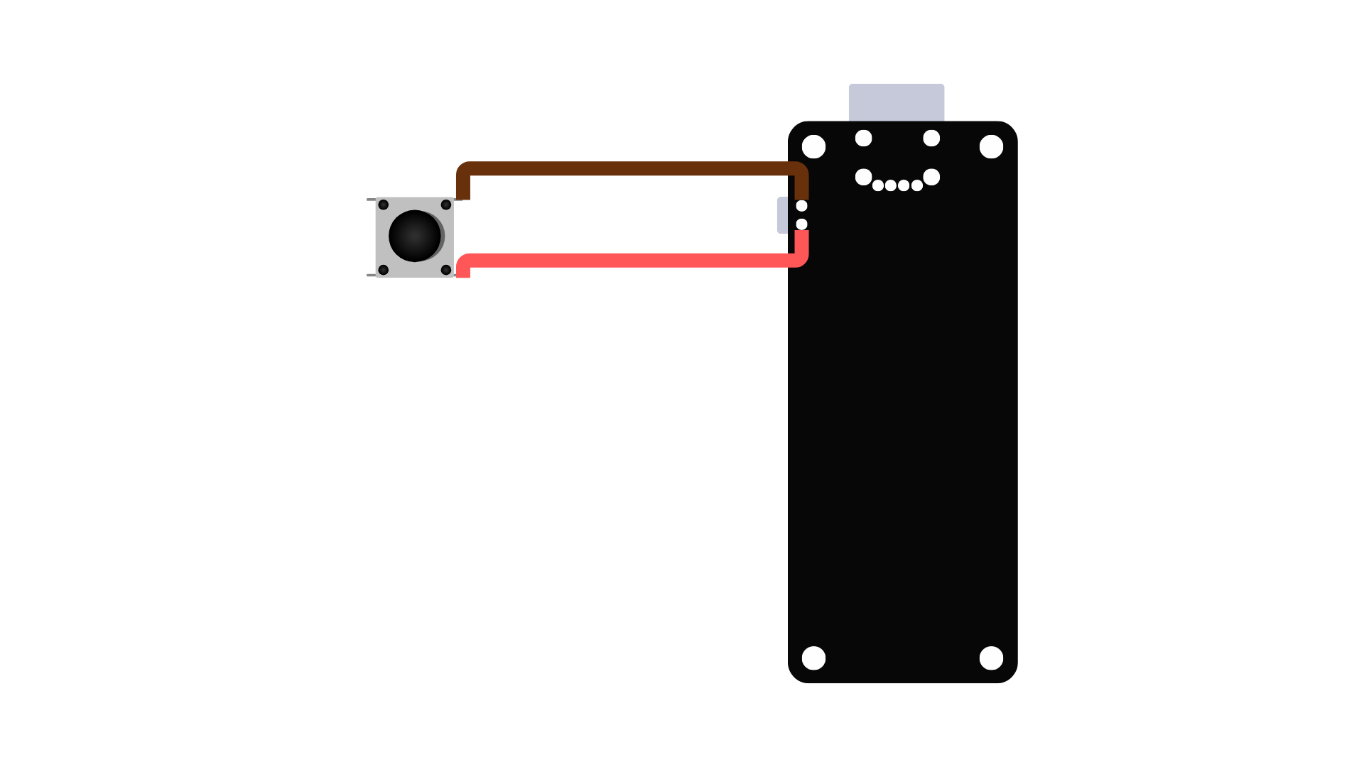
The battery management board in this design includes a small push button for powering the robot ON and OFF. However, the button is not accessible due to the housing design and is too small for practical use. To address this, we will extend the functionality by adding an external tactile push button.
Requirements:
- Tactile Push Button
- Soldering kit
- Insulated wires for extending the connection
Steps:
- Identify the tiny built-in push button on the battery management board.
- Note its connection points (two terminals).
- Attach two wires to the push button terminals. Ensure the wires are of sufficient length.
- Solder the free ends of the wires from the external push button to the same terminals as the connection diagram.
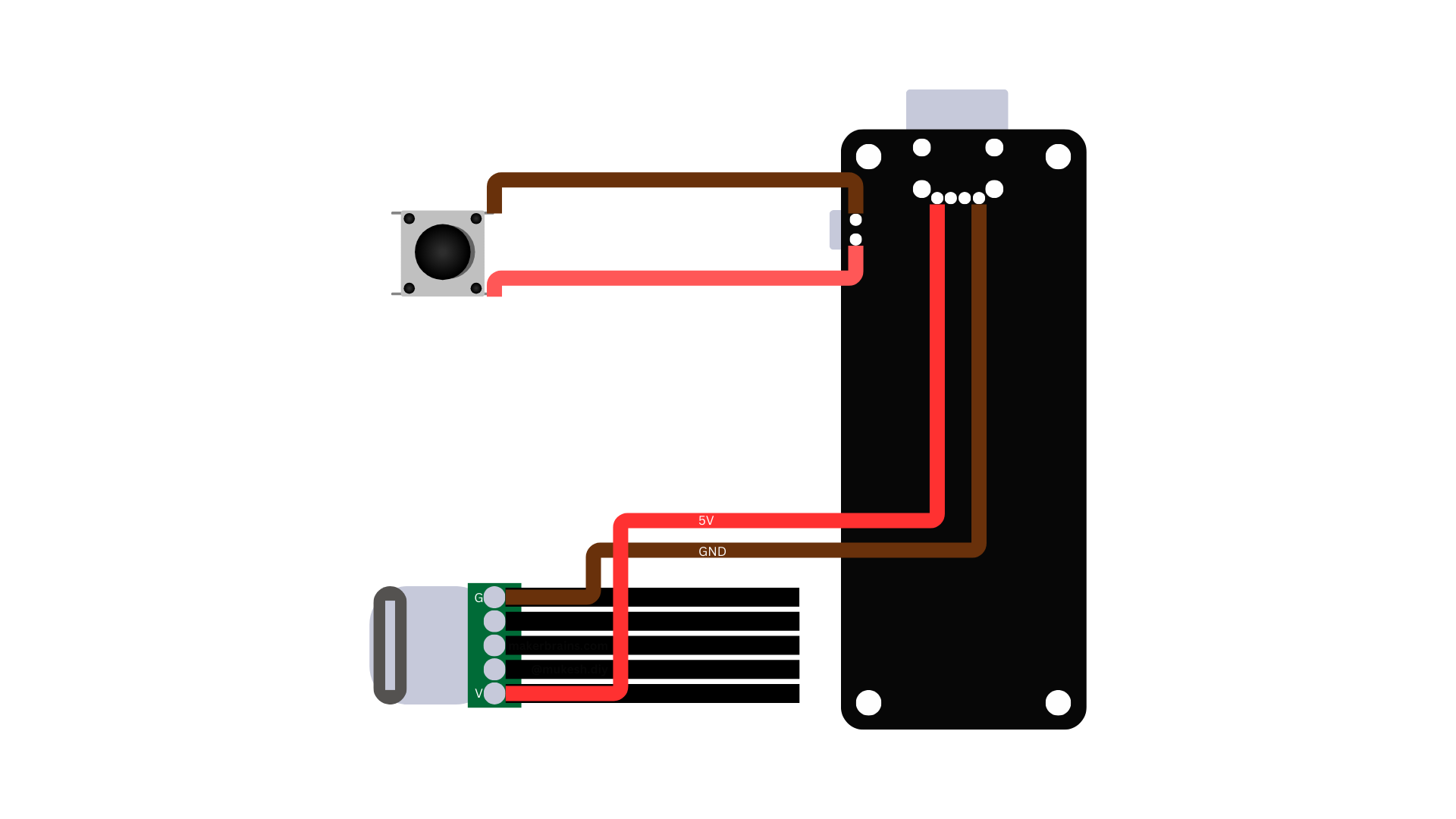
In this step, we will prepare the Unihiker board's power supply using the battery management board and ensure seamless programming through the same USB Type-C connector. By creating a custom extended connector, we will allow simultaneous power delivery from the battery pack and access to the Unihiker's USB Type-C port for programming.
Requirements:
- USB Type-C extension cable.
- Battery management board.
- Soldering kit (soldering iron, solder wire, heat shrink tubing, etc.).
- High-quality wires (to handle power load).
Steps:
- Take the USB Type-C extension cable and strip the insulation near the Female Connector end.
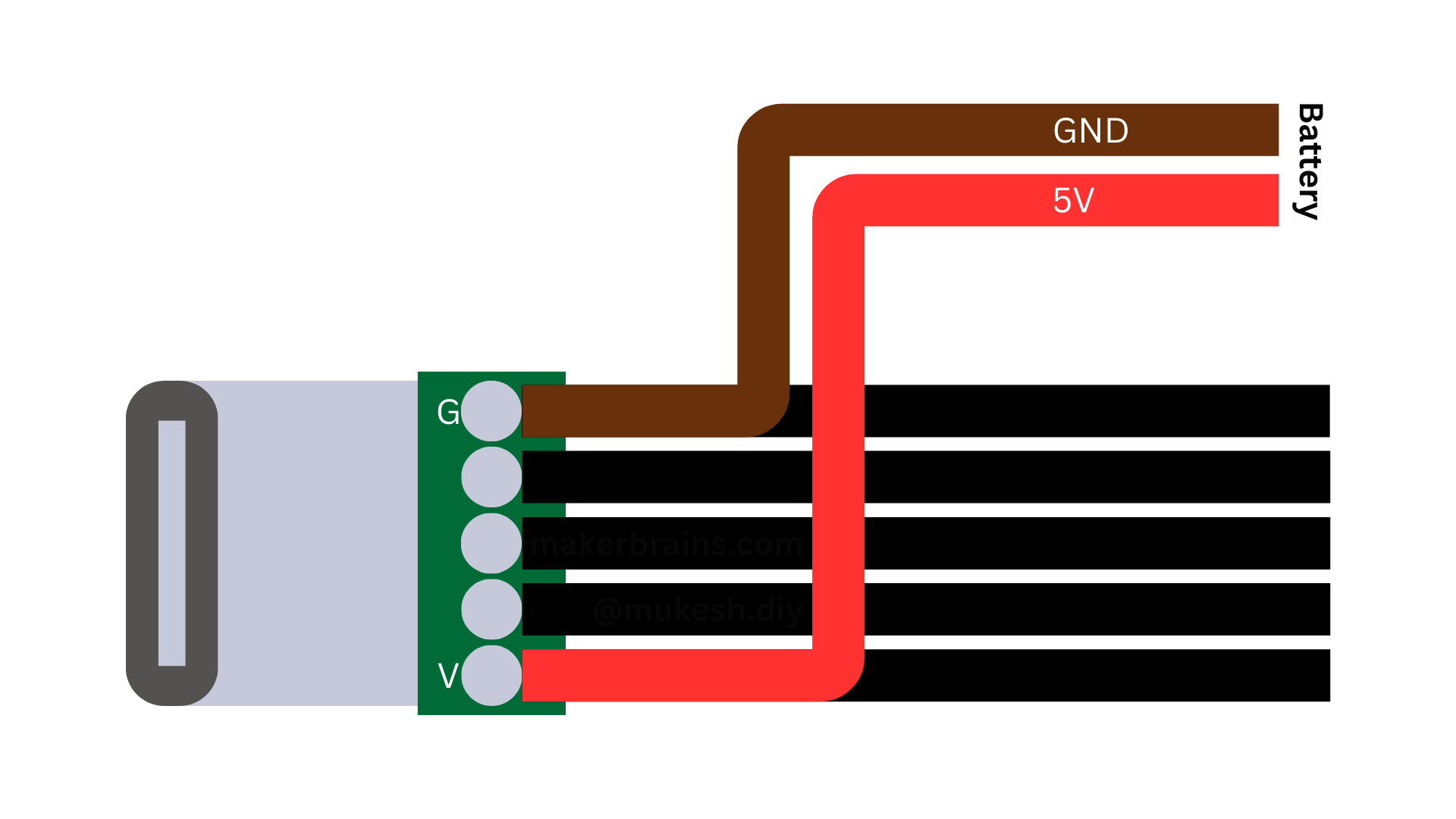
- Identify the G(GND) and V(Vcc) terminals.
- Solder two high-quality wires to the GND and VCC terminals of the Female Connector.
- Take the open ends of the wires soldered to the USB connector and attach them to the GND and 5V output terminals on the battery management board.
- Refer to the connection diagram for clarity.
- Use heat shrink tubing or insulation tape to cover the exposed soldered connections on the USB Type-C extension cable.
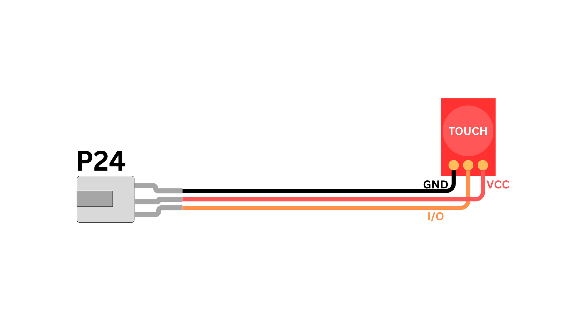
Requirements:
- Touch Sensor module
- Compatible connector (taken from the altered Unihiker connectors from Step 3)
- Soldering kit
- Jumper wires (if needed)
Steps:
- Take one of the unused connectors prepared in Step 3.
- Solder the wires from the connector to the touch sensor pins as shown in the circuit diagram above.
In this step, you will program the Unihiker board and test the circuit connections:
Set Up Connections:
- Connect all servos & touch sensor as shown in above diagram and Type-C battery pack that you prepared in earlier steps.
- Do not solder the open wire for the 4th servo yet.
Install Mind+:
- Download and install the Mind+ software from https://mindplus.cc/en.html.
- Launch the software after installation.
Prepare the Unihiker in Mind+:
- Connect the Unihiker to your PC using a USB cable.
- In Mind+, click on "Extensions" located in the bottom-left corner.
- Select "Unihiker" from the list, then click "Back" to return to the main menu.
Enable Code Mode:
- In Mind+, click on "Code" to switch to the coding interface.
- Connect to the Remote Terminal by selecting the correct COM port for the Unihiker.
- Once connected, you should see the Unihiker's file system displayed on the right-hand side.
Upload the Code:
- Download the provided folder from the Tillu GitHub Repository.
- Unzip the downloaded files to access the Tillu folder.
- Drag and drop the entire Tillu folder into the Unihiker's file system. This will upload all the necessary files and modules to the Unihiker.
Run a Test Program:
- Open the forward.py file located in the Tillu folder and run the program.
Test with the Battery Pack:
- Unplug the Unihiker from the PC.
- Turn on the battery module. The Unihiker should power on.
- Use the navigation buttons on the Unihiker to locate the forward.py file in the root folder.
- Select and run the program directly on the Unihiker.
- The servos should respond, and the touch sensor should register inputs.
- If any component doesn’t respond as expected, double-check the connections, wiring.
- Ensure the battery pack is sufficiently charged before testing.
Materials Needed:
- Unihiker board
- 3D-printed Unihiker mount
- 3 x M3 screws
- Battery pack
Steps:
- Connect the Type-C cable from the battery pack to the UniHiker board through the designated slot in the mount.
- Position the 3D-printed Unihiker mount so that it aligns with the mounting holes on the Unihiker board.
- Use the 3 M3 screws to fasten the mount to the Unihiker board.
- Take the touch sensor and apply a small amount of glue.
- Position the touch sensor onto the housing body, hold it in place for a few seconds until the glue sets.
In this step, you'll securely mount the battery pack to the robot's housing:
Materials Needed:
- Battery management board
- Second Type-C extension cable
- M2 screws
- Screwdriver
Steps:
- Take the second Type-C extension cable, plug it into the battery management board securely.
- Align the battery pack with the pre-designed screwing holes on the housing.
- Using M2 screws, attach the battery pack to the housing.
In this step, we will attach the hip servo motors to the robot's main body:
Materials Needed:
- 2 Servo motors (hip motors)
- M2 screws (from the servo pack)
- Small screwdriver
The servo motors cannot be directly mounted into the main body slots because the servo wires on the side collide with the walls of the slot.
To resolve this, we need to temporarily disassemble part of the servo motor housing.
Steps:
- Remove the screws holding the bottom cover of each servo motor using a screwdriver.
- Carefully separate the bottom part of the servo motors.
- Place the bottom part of the servo motor housing into the slot in the main body first.
- Align the servo motor with the slot and gently position it|
- Once the servo motor is positioned correctly, reattach the bottom part to the servo motor.
- Tighten the screws you removed earlier to close the servo housing securely.
- Use the M2 screws provided in the servo pack to attach the servo motor to the main body.
Materials Needed:
- 2 Servo motors (connected to one common connector)
- 2 Servo motor housings (left and right)
- 2 Servo motor covers (left and right)
- M2 screws (from the servo pack)
- Quick glue
Steps:
- Take the two servo motors previously connected to a common connector and the foot servo motor 3D printed parts.
- Insert each servo motor into its designated housing, ensuring the orientation aligns with the housing structure.
- Use the M2 screws from the servo pack to fasten each servo motor to its housing.
- Take the cover, align the shafts and snap the covers onto the housings by pressing them gently.
- Apply a small amount of quick glue around the edges of the covers where they meet the housings.
Materials Needed:
- 2 3D-printed legs
- 4 Servo arms
- M2 screws
Steps:
- Take 4 servo arms that came with the servo motos and modify two of the servo arms by cutting them in half as shown in the provided image.
- Align the servo arms with the designed slots on the 3D-printed legs, refer to the orientation in the image to position the arms correctly.
- Secure each servo arm to the leg using the M2 screws.
Use the navigation buttons on the Unihiker to access the system menu.
Enable Auto Boot:
- Navigate to Service Toggle → Auto Boot.
- Toggle the option to Enable.
Set the Program to Auto Run:
- Navigate to Run Programs → root/ → main.py.
- Select main.py and run it once.
Running the program manually confirms it as the default program to execute during boot.
Power off and restart the Unihiker to confirm that main.py runs automatically.
If the Unihiker has already been mounted to the housing, the navigation buttons may not be accessible. In this case, you can connect a mouse via the Unihiker's USB port to perform these steps as I did.
Step 15: Mounting Unihiker to the HeadTake the Unihiker board that has been previously prepared and mounted on its custom 3D-printed mount.
- Plug in all connectors, including:
- Battery pack via the Type-C connector.
- Servos 1, 2, and 3
- Touch Sensor
- Solder the 4th servo motor signal wire to P16 on the Unihiker.
- Place the Unihiker assembly, align the mounting holes within the housing (head).
- Use M2 screws to fasten the Unihiker assembly to the housing firmly.
Position Data Type-C Connector (Programming and Charging):
- Locate the Type-C data port slot on the housing.
- Carefully position the Type-C connector in its designated slot and use quick glue to secure it in place.
- Similarly, position the charging connector and secure it using quick glue.
Position the Tactile ON/OFF Push Button:
- Find the slot for the tactile ON/OFF push button on the housing.
- Position the push button in the slot and use some quick glue to ensure it stays in place.
Main Body Assembly:
- Take the main body and carefully position it onto the housing.
- Align the holes for the screws, tuck all wires neatly inside the housing, ensuring no wires are pinched.
- Make sure the two servo leg wires are routed outside the assembly from the designed slots.
- Use 5 M2 screws to secure the main body to the housing.
- Take the cover and align it with the main body assembly.
- Use 3 M2 screws to fasten the cover to the main body assembly.
Run Initialization Script:
- Plug the Unihiker into your PC.
- Run the initialize.py script. This will position all servos to a neutral 90-degree angle, ensuring proper alignment for assembly.
Attach the Legs:
- Take the two legs and mount them onto the servo motors at the 90-degree position.
- Use the screws provided in the servo pack to secure the legs firmly in place.
Attach the Feet:
- Take the foot servos that were assembled earlier.
- Position them on the legs at the 90-degree position.
- Tighten the foot servos using the same screws that were provided in the servo pack.
Mount the Headphone:
- Take the headphone and place it on the head of the robot.
Now that everything is assembled, powered on, and ready to go, you can start enjoying your Tillu robot.
Step 19: Code Explanation1. Initialization
- Imports:
- The program imports several modules:
- random, threading, and time for randomization, multitasking, and timing.
- Custom modules:
- robot_control.py for servo movements.
- facial_expressions.py for displaying video-based expressions.
- speech_text.py for voice command recognition.
- Pin for interacting with hardware buttons.
- Touch Sensor:
- Initializes a digital pin (Pin.P24) as an input touch sensor.
- Lock for Action Control:
- A threading lock (action_lock) ensures that only one action (touch or voice-based) runs at a time.
2. Key Functions
2.1. random_movement_and_expression
This function selects a random movement and a random facial expression. It performs these actions for 5 seconds:
- Randomization:
- Chooses a movement from 13 predefined dance movements (e.g., dance1, dance2).
- Chooses a facial expression (e.g., angry, heart).
- Parallel Execution:
- Movements and expressions are executed simultaneously using threads.
- Duration Management:
- Both threads run for 5 seconds before resetting to a neutral state (reset_positions and blink).
2.2. touch_listener
- Continuously monitors the touch sensor.
- If pressed:
- Ensures no other action is running (action_lock).
- Executes random_movement_and_expression.
2.3. voice_listener
- Continuously listens for voice commands using the microphone (listen_for_command).
- Command Mapping:
- Maps recognized commands (e.g. "forward", "backward", "tillu dance") to robot functions like forward() or random_movement_and_expression.
- Executes commands while ensuring no conflicts with ongoing actions.
2.4. cleanup
- A utility function for resetting the robot and stopping ongoing processes gracefully.
3. Main Program
The main() function:
- Starts with a neutral blink expression.
- Launches touch_listener and voice_listener in separate threads.
- Keeps running until interrupted (e.g., with Ctrl+C), at which point the cleanup function is called.
4. Custom Modules
4.1. robot_control.py
- Controls the robot's movement through servos.
- Movements:
- Basic (e.g., forward, backward).
- Turns (left_turn, right_turn).
- Dances (13 distinct routines using synchronized servo movements).
- Ensures smooth transitions by setting servos to rest positions (reset_positions).
4.2. facial_expressions.py
- Displays animated facial expressions using Pygame.
- Plays pre-recorded video loops (e.g., blink.mp4, angry.mp4).
- Ensures proper cleanup of resources.
4.3. speech_text.py
- Recognizes voice commands using Google Web Speech API.
- Includes noise adjustment and error handling for smoother recognition.
5. Key Features
Interactivity:
- Users can trigger actions through touch or voice.
Parallel Execution:
- Facial expressions and movements are performed concurrently.
Extensibility:
- New movements or expressions can be added by expanding their respective modules.
Error Handling:
- Handles invalid voice commands and ensures mutual exclusion between actions.
Troubleshooting and Customization:
If your robot isn't performing as expected, you may need to adjust the initial servo angles to match your robot's setup. These angles define the robot's neutral position and are configured in the reset_positions function of robot_control.py:
servo_hip_right.write_angle(95)
servo_hip_left.write_angle(85)
servo_foot_right.write_angle(85)
servo_foot_left.write_angle(100)
Try modifying these values slightly to fine-tune the robot's posture and ensure proper movement. For example:
- Increase or decrease servo_hip_* values to adjust the leg angles.
- Adjust servo_foot_* values for more precise foot positioning.
Tip: Test small increments (e.g., ±5 degrees) and observe the changes to avoid servo overloading or misalignment.
Step 20: ConclusionTillu is an exciting robotics project that combines high-quality hardware, flexible software, and custom 3D-printed design. The Unihiker board powers precise movements with servo motors, while the touch sensor adds interactivity. The robot is battery-powered, making it portable and perfect for on-the-go use.
The 3D-printed parts offer design flexibility, while Mind+ software supports both block programming and Python, making it suitable for learners of all levels. The use of Type C connectors for charging and programming simplifies setup and operation.
This project offers a hands-on learning experience, blending coding, electronics, and design in a fun and engaging way. Whether for personal use, teaching, or exploration, Tillu provides a solid foundation for anyone interested in robotics.
If you enjoyed this project, don't forget to hit the like button and leave a comment below.
Thank you! See you next time ;)



_t9PF3orMPd.png?auto=compress%2Cformat&w=40&h=40&fit=fillmax&bg=fff&dpr=2)


Comments