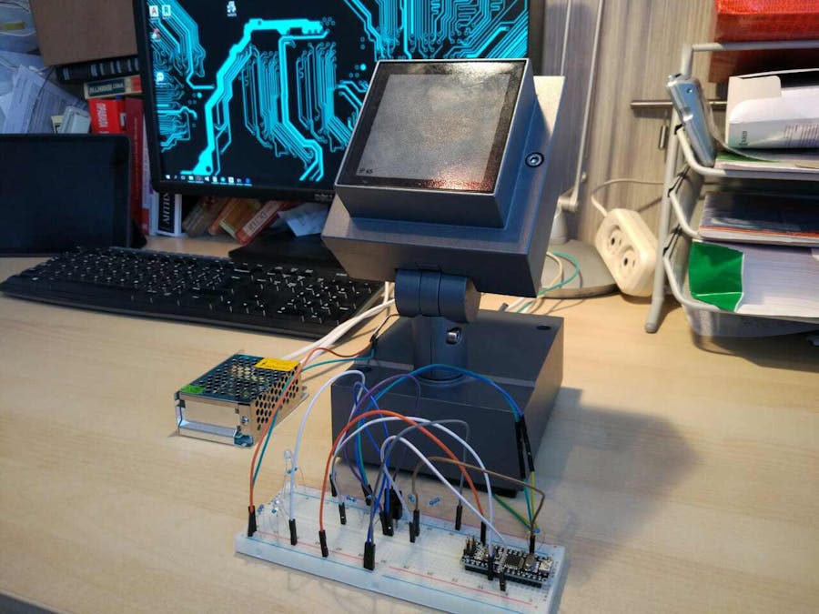
I’m an electrical engineer and after installation works extra DALI RGB luminaries remained. I didn't have DALI controller, so I decided to use Arduino Nano. First of all, I read DALI protocol documents and decided to create library to work with DALI devices. You can find DALI library in the Internet, but you need to buy special DALI master.
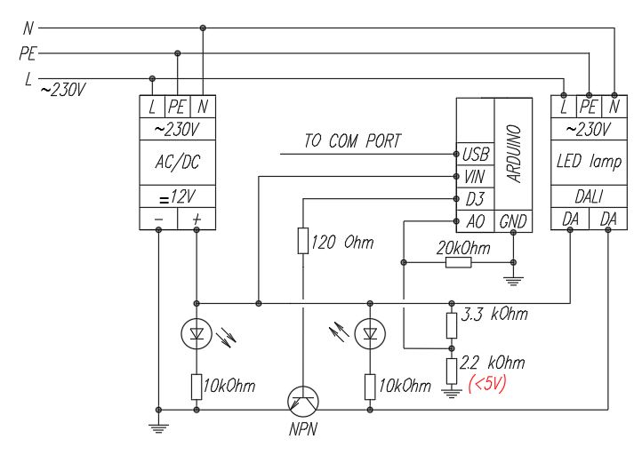
In this project I'm using simple components (see diagram in the attachment):
- ARDUINO Nano
- AC/DC converter
- LED luminaire ERCO Grasshopper with TRIDONIC driver
- NPN transistor 2SC5271
- Resistors
- LEDs for indication
DALI stands for Digital Addressable Lighting Interface. DALI is a worldwide standard, specified by the International Electrotechnical Commission (IEC). A DALI network consists of a controller and one or more luminaires that have DALI interfaces. The controller (DALI master) can monitor and control each luminaire by means of a bi-directional data exchange. The communication is via a two-wire, low-voltage bus running at a low speed (1200 bits per second). Signal levels are defined as 0±4.5 V for logical '0' and 16±6.5 V for logical '1'. Bus quiescent state is logical '1'. Manchester coding is used with 16-bit (plus start and stop) forward frames and 8-bit return frames. In Manchester coding, the bit state is defined by a transition at the center of the bit window: positive going transition = '1', negative going transition = '0'. The DALI protocol permits luminaires to be individually addressed. It also incorporates Group and Scene broadcast messages to simultaneously address multiple luminaires. A single DALI network can control up to 64 luminaires.
Every bit takes two periods. The defined bit rate of DALI is 1200 bps. So, 1 bit period is ~834 µsec. A frame is started by a start bit, and ends with two high-level stop bits (no change of phase). Data is transmitted with the MSB first. Between frames, the bus is in idle (high) state.
The settling time between two subsequent forward frames shall be at least 9.17 ms. This means that 4 forward frames with accompanying periods of 9.17 ms shall fit exactly in 100 ms.
The settling time between forward and backward frames (transition from forward to backward) shall be between 2.92 and 9.17 ms. After sending the forward frame, the master unit will wait for 9.17 ms. If no backward frame has been started after 9.17 ms, this is interpreted as “no answer” from the slave unit.
The settling time between backward and forward frames (transition from backward to forward) shall be at least 9.17 ms.
A new luminaire does not have a short address and so cannot respond to individual addressing. Since it was a new luminaire, it had to be initialized.
The DALI search process begins by assigning a 24-bit random address to up to 64 luminaires. The process is administered by DALI commands transmitted from the DALI master. This sets the luminaires to a state which permits 24-bit address searching and short address assignment. This state is limited by a 30-minute timer.
After randomizing the ballasts, the controller searches for the ballast with the lowest random number. It does this by issuing search address commands which contain the address that it is looking for, and compare commands which are queries, which get replies from all the ballasts that have that search address or lower as their random address.
Once the controller gets no replies, it backtracks one step to check the one ballast with that random address; then it assigns it a short address using a special program command which only takes effect in the ballast whose random address equals the search address (this is technically called the "selected" state). Then the controller tells that ballast to withdraw from the process so it doesn't respond to further compares this time round, and the search can continue for the next highest ballast.
After initialization we can control individual brightness of each lamp.
Using DALI librarySetup:
void setup() {
Serial.begin(74880);
dali.setupTransmit(3); //setup digital pin to transmit commands
dali.setupAnalogReceive(0); //setup analog pin to receive response
/*
Arduino must determine voltage of logic 1 and logic 0.
It depends on power converter.
*/
dali.busTest();
/*
true - reseive response with comments and text;
false - receive response from lighting fixtures with out comments and text
*/
dali.msgMode = true;
}
Commands:
/*
Transmit command.
cmd1 - address byte
cmd2 - command byte
*/
dali.transmit(cmd1, cmd2)
/*
receive response from lighting fixtures
*/
uint8_t response = dali.receive()

/*
check if lighting fixtures gave response
*/
bool response = dali.getResponse()

/*
Scan short addresses of lighting fixtures connected to bus.
*/
dali.scanShortAdd()
/*
Initialise lighting fixtures without short addresses.
*/
dali.initialisation();


Comments