Deep learning has been a pretty big trend for machine learning lately, and the recent success has paved the way to build project like this. We are going to focus specifically on computer vision and Single Shot Detection (SSD) on in this sample. In this project we will be building an AI vision kit that can be used to count items, and use WIZ750SR as a way of controlling the camera using the same network, allowing the operator to control the AI without touching it.
Single Shot MultiBox Detector (SSD)
According to Google Research Publication, Single Shot MultiBox Detector (SSD) discretizes the output space of bounding boxes into a set of default boxes over different aspect ratios and scales per feature map location. At prediction time, the network generates scores for the presence of each object category in each default box and produces adjustments to the box to better match the object shape. network also combines predictions from multiple feature maps with different resolutions to naturally handle objects of various sizes.
For the past couple of years we've been using YOLO, but with advancement of SSD it is much faster than the YOLO method. Also, SSD is a lot more efficient than traditional YOLO method as SSD uses multiple activation maps for the bounding box as YOLO uses a single activation map for prediction of classes and bounding boxes.
Equipments needed is very simple for this project, you can either do it with your computer and a USB Movidius Neural Computing Stick or Build it using Embed computing like these IoT devices.
- Up2 Board
- Vision Kit Camera
- Movidius PCIe Add-on (Or USB Neural Computing Stick)
- A screen or monitor
- WIZ750SR ETH to Serial Connector (this is an option control AI selection through local telnet
- Helium Atom and Helium Element
In this guide we will be using a SSD neural net that is pre-trained and working with Caffe. So we'd also learn how to utilize other neural network with little bit of work. The Up2 Board is already installed with Ubuntu 16.04, making things a lot more easier. On the device we can first create a folder copying everything we trained on the server. We will first install Movidius NCS SDK
cd ~/workspace
git clone https://github.com/movidius/ncsdk.git
cd ~/workspace/ncsdk
make install
Full instruction can be seen from the video below
Next we need to download all the sample apps ncappzoo, which is also created by Movidius, and the specific app we need is stream inference, which can be gotten from the example file.
cd ~/workspace
git clone https://github.com/movidius/ncappzoo.git
cd ncappzoo
make
cd caffe
make
This should be able to get the entire software stack for NCS and OpenCV, next is we can create our own folder and run based on the live-object-detector example
cd ~/workspace
git
cd ai-vision-guide
./python3 test.py
You should be able to see something like this. We are using SSD neuro network right here to identify the objects.
We can modify it further where it only detects based on label.txt that's generated from the next step.
   global lastcount
   count = 0
   file = open('label.txt','r')
   selected = file.read()
   file.close()
   for i in range( 0, output_dict['num_detections'] ):
       print( "%3.1f%%\t" % output_dict['detection_scores_' + str(i)]
              + labels[ int(output_dict['detection_classes_' + str(i)]) ]
              + ": Top Left: " + str( output_dict['detection_boxes_' + str(i)][0] )
              + " Bottom Right: " + str( output_dict['detection_boxes_' + str(i)][1] ) )
       if selected in labels[ int(output_dict['detection_classes_' + str(i)]) ]:
           count = count + 1
           # Draw bounding boxes around valid detections
           (y1, x1) = output_dict.get('detection_boxes_' + str(i))[0]
           (y2, x2) = output_dict.get('detection_boxes_' + str(i))[1]
           # Prep string to overlay on the image
           display_str = (
               labels[output_dict.get('detection_classes_' + str(i))]
               + ": "
               + str( output_dict.get('detection_scores_' + str(i) ) )
               + "%" )
           frame = visualize_output.draw_bounding_box(
                      y1, x1, y2, x2,
                      frame,
                      thickness=4,
                      color=(255, 255, 0),
                      display_str=display_str )
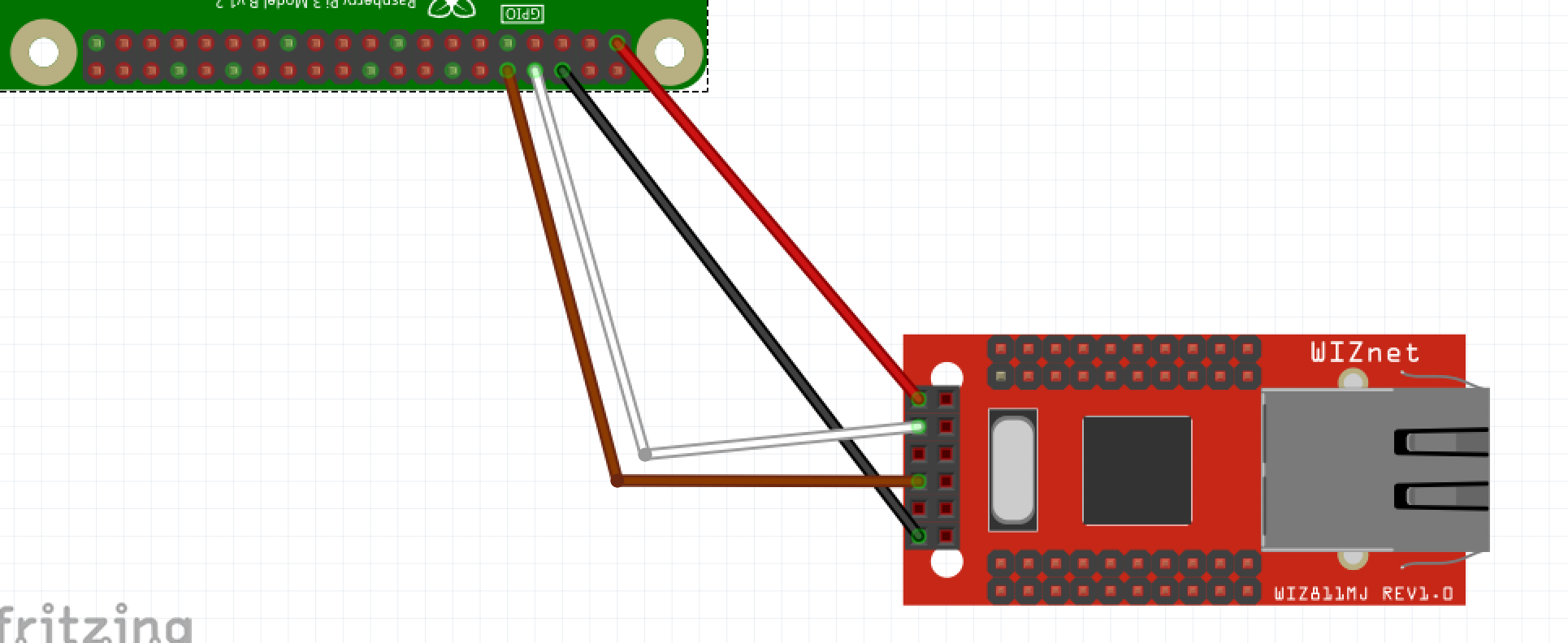
We can have the helium Pi connect on top of the Up2 board, when all done it looks something like this.
We will follow the rasperry pi SDK from Helium on
https://www.helium.com/dev/hardware-libraries/raspberry-pi
For up2 board, there is a little difference here that we need to address. We will be using "/dev/ttyS5", and we need to be in dialout permission setting in terminal, otherwise we'd have to use following code
sudo adduser up2 dialout
cd ~/workspace/
git clone --recursive https://github.com/helium/helium-cli.git
cd helium-cli
make
./helium -p /dev/ttyS5 info
This would show you whether your Helium is running correctly. On Helium Dashboard, make sure that you activate Atom
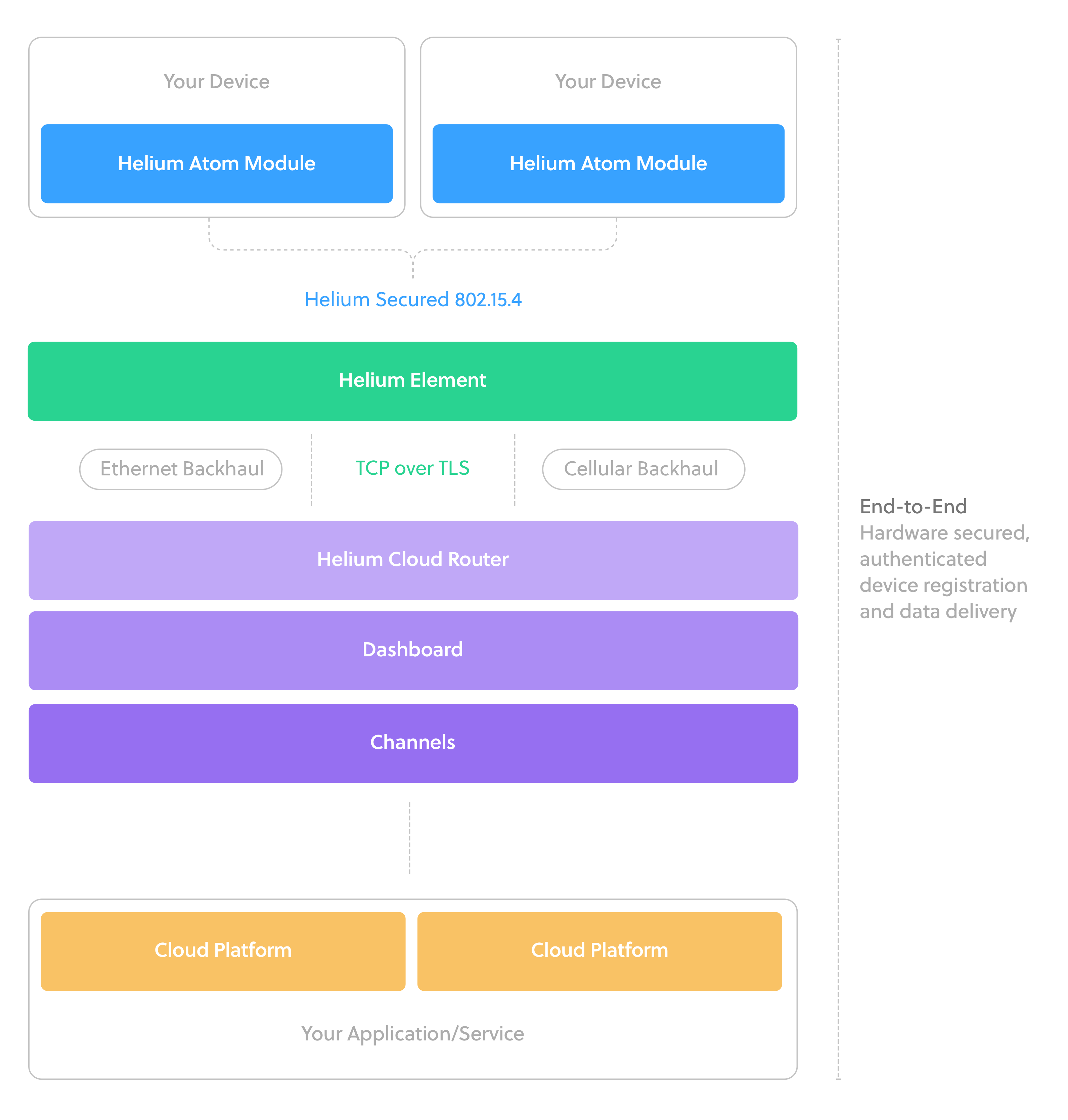
After setting up the Atom we'd also have to register Element as they are the access point, (for those who has cellular version powering it up would do).
After activating element we should see it on Access Point.
After this is all set, we can simply add in the code, first we need to install the library on up2 board for python3 since NCS SDK is running on python3
sudo pip3 install helium-client
Afterwards we need to add to our ai-vision.py. Currently there is a bug on running this, as we need 'ttyS5' on Up2 board, and 'Serial0' if you were to use Raspberry Pi. Also, the python3 code needs byte array rather than String, so we need to add b'{string}' format to make this work.
from helium_client import Helium
helium = Helium(b'/dev/ttyS5')
helium.connect()
channel = helium.create_channel(b"AI Vision")
channel.send(b'data')
Now the data should be able to upload upstream without any problem, we will need to store it so that we can run track the result as well do additional logic.
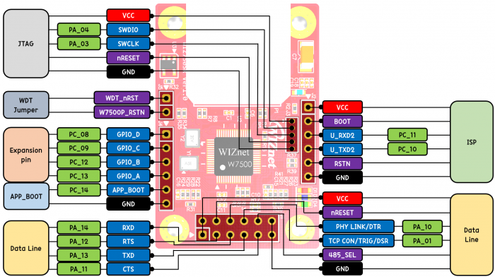
Step 4: Connect the WIZ750SRIn this guide we are using WIZ750SR as a local control unit to control what AI detects in local network, the ethernet and serial are connected to one another
With developer edition, we first can power up the WIZ750SR through micro-usb port. when everything is connected, we should see green LED on for connected to the ethernet, blue LED on for EtherNet add on working and red led on for device being powered on as figure below.
After powering on we can download the configuration tool from https://github.com/Wiznet/WIZnet-S2E-Tool-GUI to check whether the device is working. Easiest way here is to go through IP allocation via DHCP, then go back to static to auto fill out the Network configuration
The USB to UART driver can be downloaded if you are using the usb port. The Micro usb port that powers up the board will be the CP210x USB to UART Bridge used for debugging.
https://www.silabs.com/products/development-tools/software/usb-to-uart-bridge-vcp-drivers
We can use debug port to test out termite to test out the serial port, which can be downloaded from https://www.compuphase.com/software_termite.htm we should receive all the messages sending to COM port via debug usb
As for the ethernet side we used ioninja's tcp server listening http://ioninja.com/plugins/tcp-listener.html Once that's successful we can test out whether these are in Sync, this allows to communicate from Serial to Ethernet
When all set and done, the hardware should look like following
Since UP2 has same GPIO pin as Raspberry Pi, this is fairly easily done
Since we have the entire dev kit, it's much easier to embed the entire board for the demo.
Please Note: WIZ750SR is using using /dev/USB0 and Helium Atom is using /dev/ttyS5. since we've already granted permission for all the tty port from Helium code we can access directly from our code
We can use mraa library
sudo add-apt-repository ppa:mraa/mraa
sudo apt-get update
sudo apt-get install libmraa1 libmraa-dev libmraa-java python-mraa python3-mraa node-mraa mraa-tools
Afterwards, we can run the following script to see whether it works.
import serial
# this port address is for the serial tx/rx pins on the GPIO header
SERIAL_PORT = '/dev/ttyUSB0'
# be sure to set this to the same rate used on the Arduino
SERIAL_RATE = 115200
def main():
   ser = serial.Serial(SERIAL_PORT, SERIAL_RATE)
   file = open('./label.txt', 'w')
   while True:
       # using ser.readline() assumes each line contains a single reading
       # sent using Serial.println() on the Arduino
       reading = ser.readline().decode('utf-8')
       # reading is a string...do whatever you want from here
       print(reading)
       #writing to the file
       file = open('./label.txt', 'w')
       file.write(reading)
       file.close()
   ser.close()
if __name__ == "__main__":
   main()
By sending the info via ttl, we should get following, The trick here is that we will be controlling the AI, so we can store the label.txt so it can be running along side with the NCS on a different thread.
Now that we have Helium setup, we need to store the information on the cloud so that data can be stored and monitored in real time. In this guide we will be using Google IoT Core, Google gives $300 signup credit which we can use to try out different products within Google Cloud Platform, and here we will be using Google IoT Core.
We first have to create a service account under GCP
\This way we can create a new service account and get the private key in json.
After that we create a registry as well as pub/sub within Google IoT Core, in this case we use iothub as topic for the pub/sub.
After that, we can link it in our Helium portal
And now we have Helium completely connected with Google Cloud Platform's IoT Core.
If you havn't, please instead gcloud from https://cloud.google.com/sdk/install
Now that hardware part of the IoT is working, we need to set up server and data storage. The BigTable is kind of expensive and I don't have enough credits to mess around with it, in this step we will be using Node.js server and Datastore. We first need to launch a nodejs app engine like below.
Once set up, you will see the below, to start, we will use the hello world nodejs app from https://github.com/GoogleCloudPlatform/nodejs-getting-started/tree/master/1-hello-world or do a simple
cd ~/workspace/ai-vision-guide/gcloud
gcloud app deploy
Afterwards you should be able to see this under services. If you want to use any other service than default please update your app.yaml file under service: service_name, if no service name is being selected, default will be used.
Google App Engine Services
It should take a few minute to deploy, here is the code. This part can get a little complicated as you can go https://cloud.google.com/appengine/docs/flexible/nodejs/writing-and-responding-to-pub-sub-messages to find out full guide on how to get this done
We first need add following to app.yaml
env_variables:
PUBSUB_TOPIC: aivision
# This token is used to verify that requests originate from your
# application. It can be any sufficiently random string.
PUBSUB_VERIFICATION_TOKEN: YOUR_VERIFICATION_TOKEN
You can switch to any topic, token can be created for additional verification.
app.post('/pubsub/push', jsonBodyParser, (req, res) => {
if (req.query.token !== PUBSUB_VERIFICATION_TOKEN) {
 res.status(400).send();
 return;
}
// The message is a unicode string encoded in base64.
const message = Buffer.from(req.body.message.data, 'base64').toString('utf-8');
//We are pushing the data into DataStore
//This is what we will do int he next step
console.log(message);
res.status(200).send();
});
Afterwards, we need to add a subscription under
Afterwards you should see the data is hitting
Now that we have a place to push our data to, we need a Datasource for the data. we can create Datasource under GCP under Datasource. Under Datastore Entities we can create an entity.
This part is actually unnecessary since the server code automatically would generate it. But we are doing it here so that you can understand where the DataSource is being stored. After that we will be adding following code to store our data, if you get confused here feel free to check out Google's Documentation at https://cloud.google.com/nodejs/getting-started/using-cloud-datastore
First create config.json
{
"GCLOUD_PROJECT": "YOUR_PROJECT_ID",
"DATA_BACKEND": "datastore"
}
After that merge the package.json dev dependencies. in app.js first we will visit back the push message, After that we are going to store them in Datastore
app.post('/pubsub/push', jsonBodyParser, (req, res) => {
if (req.query.token !== PUBSUB_VERIFICATION_TOKEN) {
 res.status(400).send();
 return;
}
// The message is a unicode string encoded in base64.
const message = Buffer.from(req.body.message.data, 'base64').toString('utf-8');
//messages.push(message);
var data = qs.parse(message);
data.timestamp = new Date().getTime();
console.log(data);
getModel().create(data, (err, entity) => {
 if (err) {
   next(err);
   return;
 }
 res.json(entity);
});
});
Once that happens we will see our data in DataSource, the AI Vision code from IoT device is pushing every few seconds or so along with the detection
Retrieve Data: In this example we will show how to retrieve data for people and bottles, but you can use this for almost any other type.
We first have to get the index.yaml ready since we are doing WHERE command in SQL
indexes:
- kind: AIVision
 properties:
 - name: Type
 - name: timestamp
   direction: desc
After that we need to update the index by running
gcloud
To get the data, we can use following
app.get('/people', jsonBodyParser, (req, res) => {
 getModel().list(1, 'Person', (err, entities, cursor) => {
   if (err) {
     next(err);
     console.log(err);
     return;
   }
   else
   {
     if(entities.length > 0)
     {
       res.json(entities[0]);
     }
     else res.status(200).send();
   }
 });
});
app.get('/bottle', jsonBodyParser, (req, res) => {
 getModel().list(1, 'Bottle', (err, entities, cursor) => {
   if (err) {
     next(err);
     console.log(err);
     return;
   }
   else
   {
     if(entities.length > 0)
     {
       res.json(entities[0]);
     }
     else res.status(200).send();
   }
 });
});
We now have IoT inside GCP from end to end, only thing left is display the data, use following code to get the latest data which can be displayed over the webpages. We wrote a basic page from that can run locally.
We use following code WIZ750SR on local node server to access the socket. This allows everything to be controlled locally.
var client = new net.Socket();
client.connect(5000, '192.168.1.81', function() {
 console.log('Connected');
});
client.on('close', function() {
 console.log('Connection closed');
});
router.get('/setCamera', function (req, res) {
 var query = req.query.id + '\n';
 client.write(query);
 res.send(query);
});
At the same time, we can access the server via
   $( "#btnPeople" ).click(function() {
     $.ajax({
       url:"http://0.0.0.0:8888/setCamera?id=Person",
       success:null
     });
   });
   $( "#btnBottle" ).click(function() {
     $.ajax({
       url:"http://0.0.0.0:8888/setCamera?id=Bottle",
       success:null
     });    });
   $( "#btnCars" ).click(function() {
     $.ajax({
       url:"http://0.0.0.0:8888/setCamera?id=Car",
       success:null
     });
   });
Now you should have everything working, using Serial to Ethernet to control AI, and passing AI's data to Google IoT Core through Helium IoT Kit.
WIZ750SR creates unique IP and socket port, which is fairly easy to setup the camera over ip.
a. Installing motion on ubuntu:
sudo apt-get update
sudo apt-get install motion
b. Copy configure files:
mkdir .motion
sudo cp /etc/motion/motion.conf ~/.motion/motion.conf
c. Configuring the file, for those who are familiar with ubuntu can install Sublime to do easier text editing, otherwise we can edit it inside command line.
sudo nano ~/.motion/motion.conf
d. After plugging in camera, we can change the following lines in motion.conf
This is to put it in the background mode:
# Start in daemon (background) mode and release terminal (default: off) daemon on
This is to use Camera's camera view.
# Videodevice to be used for capturing  (default /dev/video0)
# for FreeBSD default is /dev/bktr0
videodevice /dev/video0
Changing the width and height, 1280 x 720 worked great for me, but you can play around with the dimensions to see what fits your need.
# Image width (pixels). Valid range: Camera dependent, default: 352
width 1280
# Image height (pixels). Valid range: Camera dependent, default: 288
height 720
I set this to 30, the higher you set the number the more computing power it would require. You can play around to see what the benchmark for it, but 30 has worked great for me.
# Maximum number of frames to be captured per second.
# Valid range: 2-100. Default: 100 (almost no limit).
framerate 30
Since we are always streaming camera, we use 5000 as previously setup in WIZnet
###########################################################
# Live Stream Server
############################################################
# The mini-http server listens to this port for requests (default: 0 = disabled)
stream_port 5000
# Quality of the jpeg (in percent) images produced (default: 50)
stream_quality 50
# Output frames at 1 fps when no motion is detected and increase to the
# rate given by stream_maxrate when motion is detected (default: off)
stream_motion off
# Maximum framerate for stream streams (default: 1)
stream_maxrate 60
# Restrict stream connections to localhost only (default: on)
stream_localhost off
You can then run ifconfig and figure out the ip address and run in terminal, the port will be 5000.
motion
If there are no errors, it's easy to check the camera from your computer using the ip, fix the errors such as permission problems if there are any. motion.conf is being attached in the code section, you can check out more settings there.


.png?auto=compress%2Cformat&w=48&h=48&fit=fill&bg=ffffff)


Comments
Please log in or sign up to comment.