Updated for 2019 China-US Young Maker Competition
Sitting and Health ProblemsIn today's world, everywhere is an office. From working at the office to coffee shops, airplanes or hotel lobbies, poor ergonomics makes its mark on our spines.
According to multiple studies, prolonged sitting in general is really bad for your health. Some studies even show that sitting can be as bad as smoking. There are solutions out there that reminds you such as a smart watch, Alexa, or computer notification, they all need users to be actively engaged, wearable devices requires habit change and alarms/notifications are often ignored.
Concept of Smart Chair
Our concept begin with a thought: If the chair is smart, it should have it's owner's best interest in mind. So if the owner of the chair is sitting too long, the chair can simply vibrate until the owner stands up again. This is a something simple and can be accomplished through MAX32620FTHR board. In this article we will be writing a step by step guide on how to build such smart chair.
Step 1: Set Up Arduino Software Environment
MAX32620FTHR supports both mbed and Arduino IDE, for this article we will focus on Arduino environment since at time of this writing, this is still relatively uncommon to find online and I hope this article helps others to create projects like this using MAX32620FTHR.
To setup Arduino IDE for the board, you can follow the basic instructions from https://github.com/MaximIntegratedMicros/arduino-max326xx, or here is the simplified walkthrough.
Under preference, first add the following into File->Preference
https://raw.githubusercontent.com/maximintegratedmicros/arduino-collateral/master/package_maxim_index.json
Then go to Tools->Board->Board Manager and enter maxim and install the latest board support as following image
After installing, we have can select MAX32620FTHR(Native USB Port) under board and "DAPLink" under Programmer
Important: The Port doesn't have to show up with anything under Native USB Port, and your computer should see "Bootloader" as an additional drive. This is a simple and straight forward way of doing plug and play on the MAX32620FTHR without any additional adapters such as PICO.
If everything is setup correctly, we can now load simple programs like Blink which the device should simple blink red led.
To reset the boot for the board, all you have to do is disconnect the power, hold the boot button and connect to power again, the board should reset to the earlier stage.
The MAX32620FTHR digital output pins are listed under https://github.com/MaximIntegratedMicros/arduino-max326xx/wiki/MAX32620FTHR
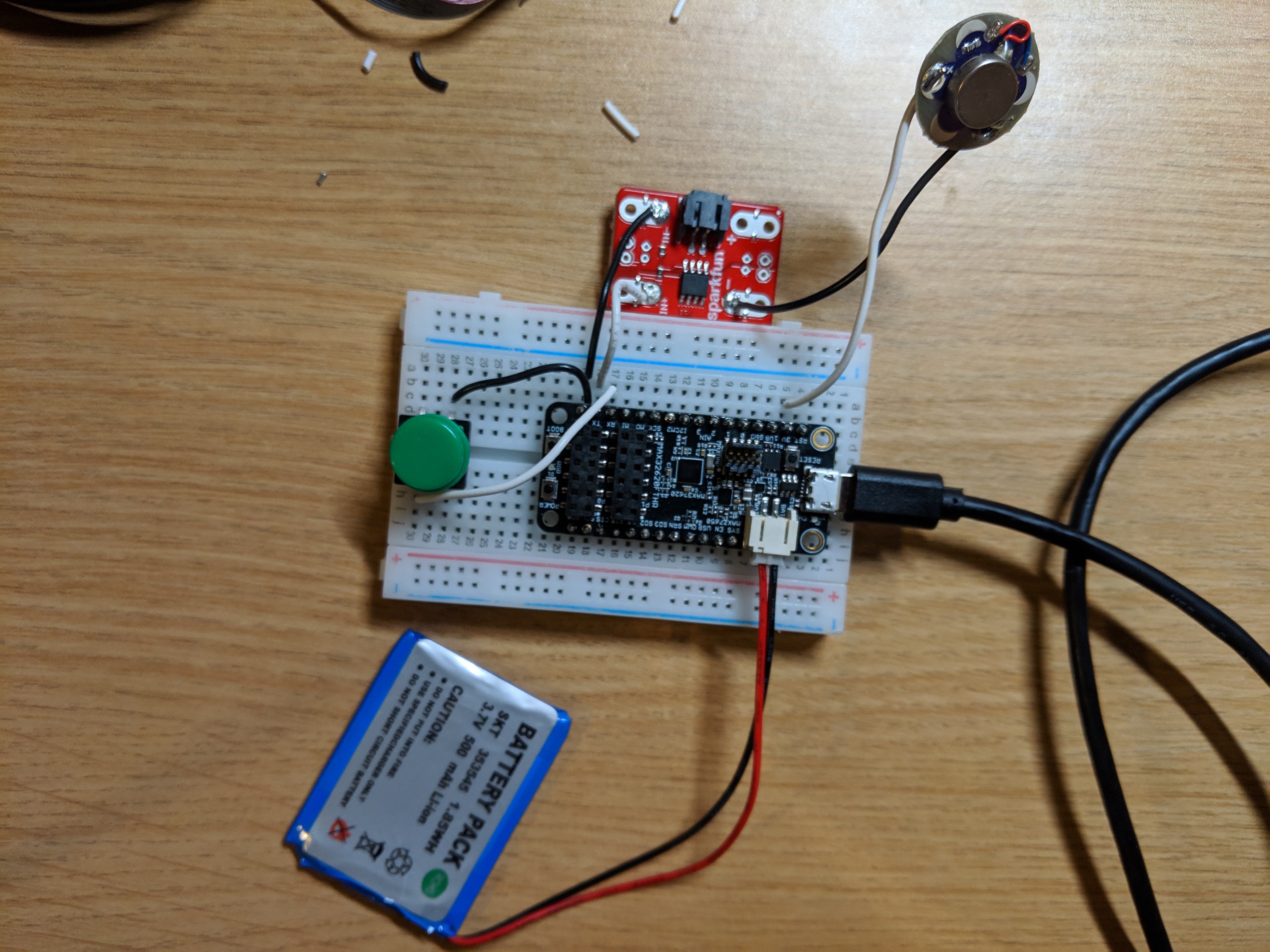
The output pins doesn't really have enough current to power up the motor, so we added additional MOSFET to make it running.
The IN- will be connected to ground, the IN+ will be connected to pin 25, - will be connected motor - and positive will be sourcing from the 3.3v coming out of the board.
We can also put green lights on the blink by setting pin 2 from the board for user LED. To do that we simply do the following
 pinMode(21, OUTPUT); // swap this out with original pinmode
 digitalWrite(21, HIGH); // write to 21 instead of LED_BUILTIN
 digitalWrite(21, LOW); // write to 21 instead of LED_BUILTIN
When all said and done we should see the following, with motor vibrating and green LED blinking.
The chair needs to know when a person is sitting on it, to do this, to do this, for this project let's just do something simple as a button, as you sit down you will be sitting on the pressure sensor like the button itself, and we will be using it as input with following code on pin 24.
int val = 0;
pinMode(24, INPUT_PULLUP);
val = digitalRead(24);     // read the input pin
 if(val == LOW)
 {
    //code
 }
The MAX32620FTHR can be powered by 3.3v-5v battery, a smart chair should be able to power itself. However, we do need to enable the pin18 in order to activate battery support. We can simply add following line of code in the setup()
pinMode(18, OUTPUT);
This is required for the device to have battery power.
Step 5: CodeIn real world if you sat for 30 minutes you should be getting up, for the simulation purposes we are going to sit for 3 seconds, and if its over 3 seconds, the LED will show up and vibration motor will be activated. to do the following we have the entire arduino C code in place.
int val = 0;
int timer = 0;
void setup() {
 pinMode(20, OUTPUT);
 pinMode(21, OUTPUT);
 pinMode(22, OUTPUT);
 pinMode(24, INPUT_PULLUP);
 pinMode(25, OUTPUT);
   pinMode(18, OUTPUT); //for battery
}
// the loop function runs over and over again forever
void loop() {
  digitalWrite(21, LOW); //green led to show that this is working
 val = digitalRead(24);     // read the input pin
 if(val == LOW)
 {
     timer++;
}
else
{
     timer = 0;
     digitalWrite(20, HIGH);
     digitalWrite(22, HIGH);
     digitalWrite(25, LOW);
}
if(timer >= 30)
{
       digitalWrite(20, LOW);
     digitalWrite(22, LOW);
     digitalWrite(25, HIGH);
}
 delay(100);
}
And now this should pretty much work.
Step 6: Build a LEGO Chair PrototypeI have to admit my LEGO skill is extremely bad, but I am sure you guys will build out a much prettier chair than me using LEGOs. Idealy the chair top will be LEGO pieces too, but due to time constraint I am going to use the breadboard as the chair top.
Hopefully this guide helps you to build out something great.
And the demo:


Comments
Please log in or sign up to comment.