Hackster is hosting Hackster Holidays, Ep. 6: Livestream & Giveaway Drawing. Watch previous episodes or stream live on Monday!Stream Hackster Holidays, Ep. 6 on Monday!
OzzMaker
Published © GPL3+

Double Tap Recognition with BerryIMUv3

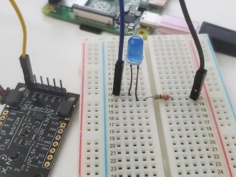
The BerryIMUv3 makes it easy to detect double taps, which can be used to control the GPIO of an a Raspberry Pi.

BeginnerProtip1 hour353
Double Tap Recognition with BerryIMUv3

Things used in this project

Hardware components

BerryIMU
×1
Raspberry Pi 4 Model B
×1
LED (generic)
LED (generic)
×1
Resistor 330 ohm
Resistor 330 ohm
×1
OzzMaker QWIIC connector
×1

Story

Read more

Schematics

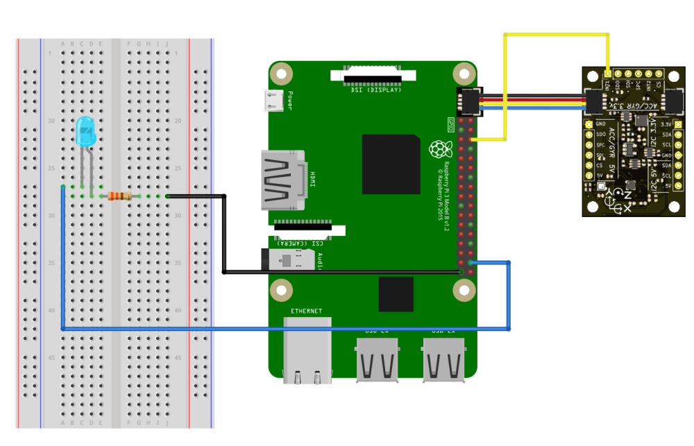
doubletapqwiic_CMafasVEbS.png

Code

Code snippet #1

Plain text
import signal
from LSM6DSL import *
import sys
import RPi.GPIO as GPIO 
import smbus

bus = smbus.SMBus(1)

LED_ON = 0                                                           #Used to track of the current state of the LED
INTERRUPT_PIN = 12                                                   #The interrupt pin which will be connected to the IMU
LED_PIN = 38                                                         #The pin which will be driving the LED

#Used to clean up when Ctrl-c is pressed
def signal_handler(sig, frame):
    GPIO.cleanup()
    sys.exit(0)
    

#Used to write to the IMU
def writeByte(device_address,register,value):
    bus.write_byte_data(device_address, register, value)


def LEDnotification(channel):
	global LED_ON
	if LED_ON:
		GPIO.output(LED_PIN,0)
		LED_ON = 0
	else:
		GPIO.output(LED_PIN,1)
		LED_ON = 1


writeByte(LSM6DSL_ADDRESS,LSM6DSL_CTRL1_XL,0b01100000)                 #ODR_XL = 416 Hz, FS_XL = +/- 2 g
writeByte(LSM6DSL_ADDRESS,LSM6DSL_TAP_CFG,0b10001110)                  #Enable interrupts and tap detection on X, Y, Z-axis
writeByte(LSM6DSL_ADDRESS,LSM6DSL_TAP_THS_6D,0b10001100)               #Set tap threshold
writeByte(LSM6DSL_ADDRESS,LSM6DSL_INT_DUR2,0b01111111)                 #Set Duration, Quiet and Shock time windows
writeByte(LSM6DSL_ADDRESS,LSM6DSL_WAKE_UP_THS,0b10000000)              #Double-tap enabled 
writeByte(LSM6DSL_ADDRESS,LSM6DSL_MD1_CFG,0b00001000)                  #Double-tap interrupt driven to INT1 pin


GPIO.setmode(GPIO.BOARD) # Use physical pin numbering
GPIO.setup(INTERRUPT_PIN, GPIO.IN, pull_up_down=GPIO.PUD_DOWN)
GPIO.setup(LED_PIN, GPIO.OUT)
GPIO.output(LED_PIN, 0)
GPIO.add_event_detect(INTERRUPT_PIN, GPIO.RISING, callback=LEDnotification, bouncetime=300)


while True:
    signal.signal(signal.SIGINT, signal_handler)
    signal.pause()

Double tap recognition

Python
import signal
from LSM6DSL import *
import sys
import RPi.GPIO as GPIO 
import smbus

bus = smbus.SMBus(1)

LED_ON = 0                                                           #Used to track of the current state of the LED
INTERRUPT_PIN = 12                                                   #The interrupt pin which will be connected to the IMU
LED_PIN = 38                                                         #The pin which will be driving the LED

#Used to clean up when Ctrl-c is pressed
def signal_handler(sig, frame):
    GPIO.cleanup()
    sys.exit(0)
    

#Used to write to the IMU
def writeByte(device_address,register,value):
    bus.write_byte_data(device_address, register, value)


def LEDnotification(channel):
	global LED_ON
	if LED_ON:
		GPIO.output(LED_PIN,0)
		LED_ON = 0
	else:
		GPIO.output(LED_PIN,1)
		LED_ON = 1


writeByte(LSM6DSL_ADDRESS,LSM6DSL_CTRL1_XL,0b01100000)                 #ODR_XL = 416 Hz, FS_XL = +/- 2 g
writeByte(LSM6DSL_ADDRESS,LSM6DSL_TAP_CFG,0b10001110)                  #Enable interrupts and tap detection on X, Y, Z-axis
writeByte(LSM6DSL_ADDRESS,LSM6DSL_TAP_THS_6D,0b10001100)               #Set tap threshold
writeByte(LSM6DSL_ADDRESS,LSM6DSL_INT_DUR2,0b01111111)                 #Set Duration, Quiet and Shock time windows
writeByte(LSM6DSL_ADDRESS,LSM6DSL_WAKE_UP_THS,0b10000000)              #Double-tap enabled 
writeByte(LSM6DSL_ADDRESS,LSM6DSL_MD1_CFG,0b00001000)                  #Double-tap interrupt driven to INT1 pin


GPIO.setmode(GPIO.BOARD) # Use physical pin numbering
GPIO.setup(INTERRUPT_PIN, GPIO.IN, pull_up_down=GPIO.PUD_DOWN)
GPIO.setup(LED_PIN, GPIO.OUT)
GPIO.output(LED_PIN, 0)
GPIO.add_event_detect(INTERRUPT_PIN, GPIO.RISING, callback=LEDnotification, bouncetime=300)


while True:
    signal.signal(signal.SIGINT, signal_handler)
    signal.pause()

Credits

OzzMaker

OzzMaker

6 projects • 1 follower

Comments