

Hardware components | ||||||
_ztBMuBhMHo.jpg?auto=compress%2Cformat&w=48&h=48&fit=fill&bg=ffffff) |
| × | 1 | |||
 |
| × | 1 | |||
 |
| × | 1 | |||
Software apps and online services | ||||||
 |
| |||||
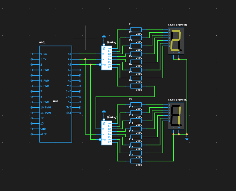
A simple example of how to use Arduino and two 8-bit shift registers to control two 7-segment LED displays to show numbers. By cycling through the numbers 0 to 9, you can observe the digits changing on the displays.
Online SimulationThe code begins by defining the pins connected to the shift registers:
data Pin (Pin A5): This is the serial data input pin for the shift register.
clock Pin (Pin A4): This is the clock input pin for the shift register.
reset Pin (Pin A3): This is the reset pin for the shift register, used to clear the register before sending new data.
Display CharactersThe numbers array defines the hexadecimal codes for the digits 0 through 9 for a common cathode 7-segment display. These codes indicate which segments should be lit to display each digit.
Setup FunctionIn the setup function, all defined pins are set to output mode.
Loop FunctionThe loop function contains an infinite loop called the displayNumber function, which displays two digits on the 7-segment displays, with each digit being displayed for 1 second (1000 milliseconds).
DisplayNumber FunctionThe display Number function takes two parameters, num1, and num2, which are the digits to be displayed on the two 7-segment displays. The function first resets the shift register by pulling the reset pin low and then high. It then sends the data for each digit to the corresponding shift register and locks it in with the latch pin.
ShiftOut FunctionThe shift-out function is used to send a byte of data to the shift register. It loops through 8 times, sending each bit of the data byte to the data pin and toggling the clock pin to shift the data.
Check more simulation projects here


Comments