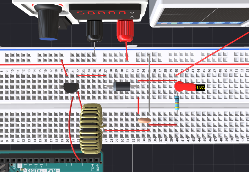
A Buck-Boost Converter is a type of DC-DC converter that can step up (boost) or step down (buck) an input voltage, and in some configurations, it can also invert the output voltage. This tutorial will guide you through the design and implementation of a Buck-Boost Converter with an inverted output voltage. We'll cover the principles of operation, component selection, circuit design, and practical implementation.
Required Components- Inductor: Choose an appropriate inductor based on your voltage and current requirements.
- Capacitors: Input and output capacitors are necessary for smoothing the voltage.
- Diode: A Schottky diode is preferable due to its low forward voltage drop.
- Switching Element: A MOSFET or BJT that can handle the input voltage and output current.
- Microcontroller or PWM IC: This is used to generate the PWM signal to control the duty cycle.
- Resistors: For voltage sensing and feedback.
- Voltage Reference: To compare and stabilize output voltage.
- Breadboard/PCB & connecting wires
Basic Operation: A Buck-Boost Converter intermittently connects and disconnects a voltage source to an inductor. When the switch is closed, energy is stored in the inductor. When the switch opens, the inductor discharges its energy to the output through the diode, generating a voltage output that can be either higher or lower than the input voltage.
Inverted Output Voltage: The key to obtaining an inverted output voltage lies in how the output is taken from the circuit. In a typical configuration, the output voltage is derived from the opposite side of the inductor and diode, which results in an inverted output.
Duty Cycle Control: The output voltage magnitude is controlled by adjusting the PWM signal's duty cycle to the switching element. A higher duty cycle reduces the output voltage magnitude, while a lower duty cycle increases it.
Feedback and Control Circuit: Use a voltage divider (R1 and R2) to sense the output voltage. Connect this to the microcontroller or PWM IC to compare the output voltage with a reference voltage and adjust the PWM signal accordingly.
Simulate OnlineHere are the project link so you can do the online operation to have a test
https://www.pcbx.com/forum-detail/f08738955ea74c29a02e24f91e28b9ba
ConclusionIn this tutorial, you’ve learned how to design, build, and control a Buck-Boost Converter with an inverted output voltage. By systematically selecting components, creating a feedback mechanism, and programming a microcontroller, you can achieve excellent control over the output voltage.
Take the time to experiment with different load conditions and component values to further understand the behavior of your circuit. Happy tinkering!
Join the PCBX community to simulate your own projects
https://www.pcbx.com/forum?mtm_campaign=E&mtm_kwd=hack
Register now to get your first Free PCB&PCBA coupon
https://www.pcbx.com/?mtm_campaign=E&mtm_kwd=BD
While the 3D simulation feature is still a work in progress, we would love to hear your suggestions and expectations. It's an open-source community; any sharing and feedback is welcome.Your feedback will help our engineering team enhance the platform and better serve our users.Thank you!


_ztBMuBhMHo.jpg?auto=compress%2Cformat&w=48&h=48&fit=fill&bg=ffffff)


Comments
Please log in or sign up to comment.