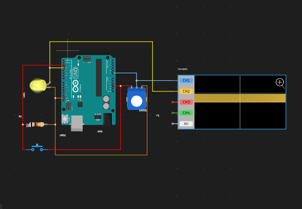
IntroductionThis project demonstrates the use of an Arduino UNO, a potentiometer, a push button, and an oscilloscope to control the brightness and blinking pattern of an LED.
DescriptionThe Arduino code initializes the pin modes and continuously reads the potentiometer's value to adjust the LED's brightness. It also checks the push button's state to toggle between two blinking modes. The analogWrite() function is used to set the LED's brightness.
The potentiometer's middle terminal voltage can be observed on an oscilloscope, showing a linear change as the knob is turned.
The push button's signal can be monitored to see the transition between LOW and HIGH states when pressed and released.
Start the simulation now, project code here.
ConclusionThis project successfully showcases how to use PCBX online simulation to control the brightness and blinking patterns of an LED using basic electronic components. By adapting the code further, you can add unique blinking patterns or connect additional LEDs.
Exploring these concepts through simulation is a fantastic way to solidify your understanding of electronics and Arduino programming.
Join our community to share your innovations and win a surprise bag.

_ztBMuBhMHo.jpg?auto=compress%2Cformat&w=48&h=48&fit=fill&bg=ffffff)


Comments