


Hardware components | ||||||
_ztBMuBhMHo.jpg?auto=compress%2Cformat&w=48&h=48&fit=fill&bg=ffffff) |
| × | 1 | |||
 |
| × | 1 | |||
 |
| × | 1 | |||
Software apps and online services | ||||||
 |
| |||||
In this tutorial, we will build a simple LED timer using an Arduino Uno, a common cathode 7-segment display, and a push-button switch. This project will help you learn about driving an LED display, handling input from a switch, and implementing basic timing functionality in Arduino.
Components Needed1. **Arduino Uno** - The microcontroller board that will control the project.
2. **Common Cathode 7-Segment Display** - The display to show the timer count.
3. **Push Button Switch** - To start and reset the timer.
4. **220 Ohm Resistors** (x7) - To limit the current to the LED segments and prevent damage.
5. **Breadboard** - For easy assembly of the circuit.
6. **Jumper Wires** - To connect everything together.
Before we start assembling, let’s outline how to connect the components:
Connections:
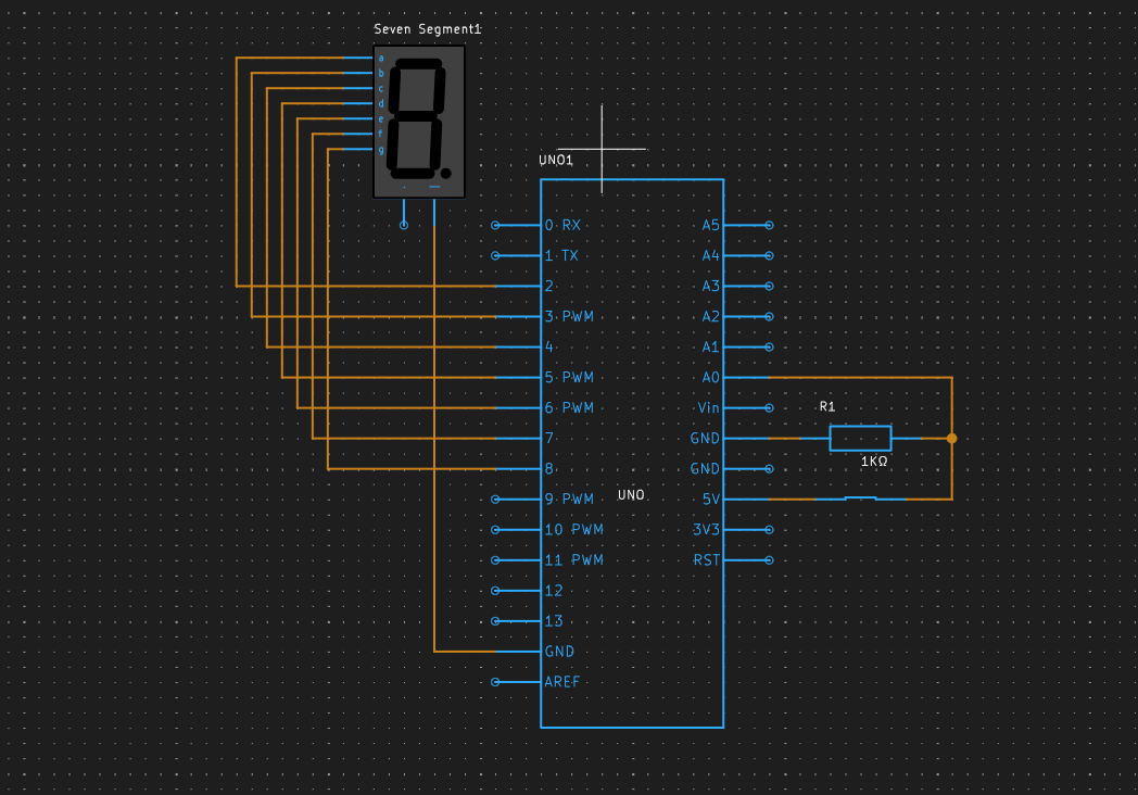
1. **7-Segment Display:**
- Connect pins a-f of the 7-segment display to digital pins D2 through D8 of the Arduino.
- Connect the common cathode pin of the display to the ground (GND) on the Arduino.
2. **Switch:**
- Connect one terminal of the push button switch to the A0 pin on the Arduino.
- Connect the other terminal of the switch to the ground (GND).
- To ensure stable readings, connect a pull-up resistor (10k ohm) from the A0 pin to the 5V pin on the Arduino.
### 7-Segment Pin Configuration:
- The pin configuration for the segments (a-g) is typically as follows (but can vary based on the model):
- `a` - Pin D2
- `b` - Pin D3
- `c` - Pin D4
- `d` - Pin D5
- `e` - Pin D6
- `f` - Pin D7
- `g` - Pin D8
Here’s a simple schematic representation:
[Arduino UNO]
D2 ----- a (7-segment)
D3 ----- b
D4 ----- c
D5 ----- d
D6 ----- e
D7 ----- f
D8 ----- g
GND ----- Common Cathode
[A0] ------ Switch ------ GND
+--(10kΩ pull-up)--- 5V
```
Step 3: Upload the Code
1. Make sure your Arduino is connected to the computer.
2. Click the upload button (right-arrow icon) in the Arduino IDE.
3. Wait for the code to compile and upload to the Arduino.
Final Steps
1. Once the upload completes, press the button switch. The 7-segment display should start counting from 0 to 9 and then reset back to 0 after reaching 9.
2. You can interrupt the counting by releasing the button. You can also modify the debounce values or timing in the code for different behavior.
Conclusion
Congratulations! You have successfully created a simple timer using an Arduino and a 7-segment display. This project introduces you to basic components like switches and displays while also providing foundational knowledge for more complex projects. Feel free to explore further by customizing the timing, adding sound, or even enhancing the display with additional features!
Simulate your timer at PCBX- https://www.pcbx.com/forum?mtm_campaign=E&mtm_kwd=hack


Comments
Please log in or sign up to comment.