

Hardware components | ||||||
_ztBMuBhMHo.jpg?auto=compress%2Cformat&w=48&h=48&fit=fill&bg=ffffff) |
| × | 1 | |||
 |
| × | 1 | |||
 |
| × | 1 | |||
 |
| × | 1 | |||
 |
| × | 1 | |||
Software apps and online services | ||||||
 |
| |||||
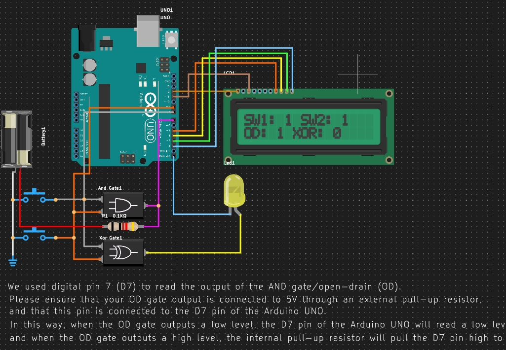
In this tutorial, we will simulate the output of an AND gate configured as an open-drain (OD) output circuit using an Arduino UNO. We will connect the output of the AND gate to digital pin 7 (D7) of the Arduino. The main concept is to use an external pull-up resistor, which will allow us to read the state of the OD gate correctly.
Circuit SetupWiring the Open-Drain AND Gate:
- Connect the output of the AND gate to digital pin 7 (D7) on the Arduino.
- Connect the output of the AND gate to one end of the external pull-up resistor.
- Connect the other end of the pull-up resistor to 5V.
- Ensure the grounds of both the AND gate and the Arduino are connected together.
Understand the Logic:
- When the AND gate outputs a low level (0), D7 will read low.
- When the AND gate outputs a high level (1), the pull-up resistor will pull D7 high, and it will read high.
PCBX provides an online simulation platform for you to test the project.
Here are the project details and code:
https://www.pcbx.com/community-detail/577ecad5656b48c6ad1b8025810be320
In this tutorial, we successfully set up a simulation of an AND gate with an open-drain output using an Arduino UNO. Utilizing an external pull-up resistor allows us to read the output states properly. You can further expand this project by changing the inputs to the AND gate and observing how the output responds accordingly.
If you have any questions or need further clarification about specific steps, feel free to ask!
Join our community to create your own innovation and win a surprise bag now. :)


Comments