


Hardware components | ||||||
 |
| × | 1 | |||
 |
| × | 1 | |||
 |
| × | 1 | |||
 |
| × | 1 | |||
 |
| × | 1 | |||
Software apps and online services | ||||||
 |
| |||||
Description
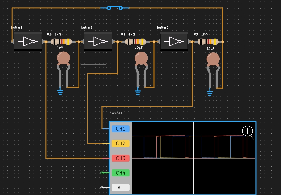
Read moreAs the signal travels through three inverters and RC filters it gets inverted and delayed (again and again). The oscillation frequency is defined by the RC time constant. Flip the switch to start oscillation. Try to build one with five inverter stages.
Setting Up the PCBX Environment- Open PCBX: Launch the PCBX simulation on your computer.
You can just use the example project or code to recreate or play:
https://www.pcbx.com/community-detail/c9f9c44aa7de4d739138956fc2e4fa82
- Create a New Project: Start a new project by selecting "My Workbench"
Run the Simulation Again:
- Start the simulation once more and observe the output waveform from the last inverter.
The ideal ring oscillator is a versatile component in electronics, applicable in both theoretical studies and practical implementations across various fields.
Join the PCBX Community to create your own innovation; for every sharing, a surprise bad will be rewarded.

33 projects • 11 followers
Customer Success: Your one-stop solution for PCB and PCBA services, plus component sourcing. Enjoy FREE online simulation and EDA.


_3u05Tpwasz.png?auto=compress%2Cformat&w=40&h=40&fit=fillmax&bg=fff&dpr=2)
Comments