It's a system that monitors the environment of kitchen. Here, only natural gas leakage level monitoring and alarming is equipped. Gas leakage can happen from faulty gas cylinders, gas pipes, valves etc.
Think, somehow a turned on gas stove's fire is extinguished (could happen by air blow, cooking spillage), natural gas will start to accumulate inside the kitchen. If such a scenario is left for a prolonged period, an air-gas explosive mixture will be created.
This is specially applicable for forgetful elderly people who might also have a weak sense of smell for gas leakage !
This basic system will alert the user, a further developed system (for commercial purpose) can shut-off gas flow, turn on ventilation fan, inform user over IoT link!
External HardwareThere are a few external hardware devices used in this project. The MQ 05 Gas Sensor (also available as Grove Module) which is sensitive to Natural Gas (Methane). Natural Gas is a commonly used stove fuel for kitchen. Anyway, there is a small electro-chemical heater inside MQ gas sensors which responds to certain types of gasses. If you use the non grove version of the sensor, a load resistor is required for adjusting sensor sensitivity/detection range. The sensor provides analog voltage as output: the higher the gas concentration, the higher is the voltage.
For displaying visual alert, there is a Red-Yellow-Green 7 dash LED bar display, which is a common anode display. It requires some external resistors to limit LED current. The alarm is generated with a high impedance piezoelectric speaker. Being high impedance makes it possible to drive with low current.
Of course there is the PSoC 4 CY8CKIT049 which breaks out the CY8C4245AXI-483 chip-32-bit PSoC ARM MCU.
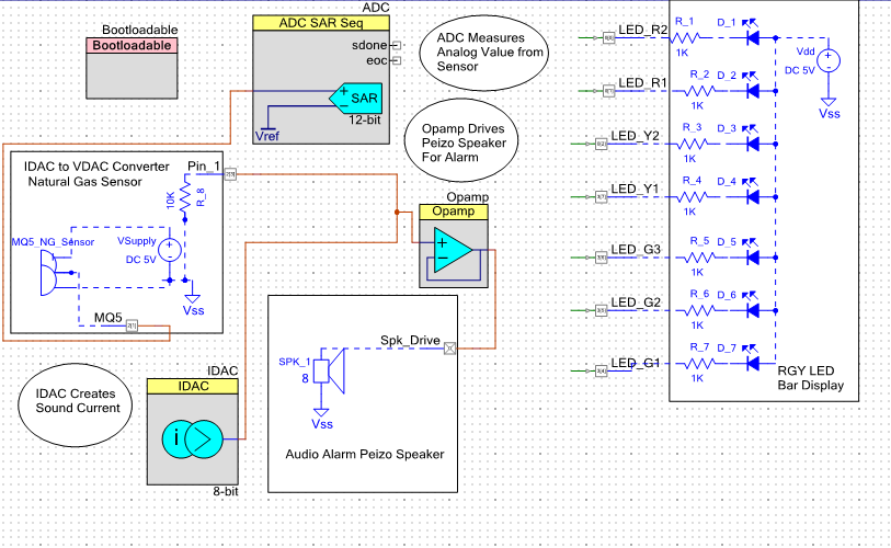
ADC, IDAC, OpAmp and some I/O pin components are utilized for this project.
12-bit ADC basically measures the Gas Sensor Analog Output. ADC range is from Ground to Rail (0V to 5V) with Vdd/2 as reference voltage, operated in unsigned, single ended mode gives full 4095 values measurable from sensor. With a pre-calibrated sensor Gas PPM levels may be possible to measure.
IDAC is used to create time varying voltage by passing through a external 10k load resistor which will make the IDAC to function like VDAC. It is possible to create sine/square/triangular/whim shaped voltage waves. Here, I created staircase-saw-tooth like voltage wave. IDAC must be configured as Source.
Internal OpAmp can drive load up to 10 mA. The OpAmp is operated voltage-follower-peizo-driver to generate sound signal. Opamp is configured in Power mode.
There are 3 Analog and 7 Digital I/O pins used to interface with external devices. One Analog input interfaces with the Gas Sensor configured in High Impedance mode with initial state as low.
One of the other two Analog pins are used to interface with 10k Current to Voltage converter resistor configured in Strong Drive mode. The other Analog pin brings out the OpAmp Output to interface with piezoelectric speaker also configured as Strong Drive mode.
The 7 Digital pins are interfaced with the LED Bar Display configures as Output, Strong Drive. Since the Bar Display is Common Anode (+), so lowering the remaining pins will cause LED glow. This is done by these 7 Digital Outputs – which is software controlled.
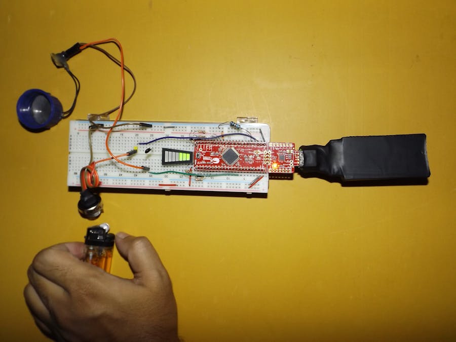
Building the ProjectThe project is built on a breadboard. CY8CKIT is placed on the breadboard with the soldered male header pins. Breadboard jumper wires are used to make electrical connections with Display, Gas Sensor, Piezo. A USB Power Bank is used to power up the project.
Working Principle & SoftwareThe working principle is super simple. Get sensor value > Show Gas Level > Buzz Alarm and the start over again.
Since I am too lazy when it comes to coding (bad habit grew from Arduino Usage-Delay/Polling/Code Space wasting/One Dimensional Thinking) and don’t like writing sleek C-Codes (let alone Assembly) that is full of interrupts, power saving, optimized, memory efficient and other stuff. The code is plain-which is kinda shame for a 32-bit ARM-PSoC MCU abused in the hand of a ignorant child. They could have probably gone to the Mars in 60’s if they had such computing power to control Apollo-11.
Anyway, first we start the Internal Hardware with Start APIs. Then we use the blocking ADC conversion and get sensor data. Then update Bar Display. If Gas concentration is too high, the IDAC value is set repeatedly with different values for each iteration of the infinite For-Loop. With the natural delays of APIs execution- I have managed to get a wave of around 4 kHz.
HardwareI have used ADC, DAC, OpAmp to emphasize analog hardware components.
IDAC and OpAmp are used to create sound tone, which could alternatively done with PWM. PSoC 4 has limited Analog Resources. PSoC 5 is the right choice for developing such devices.
Live Action!Here is a video of the system tested with Lighter Gas.
As you can see, when the gas is burning/fire is on, the sensor does not show gas level. Because when natural gas burns it creates CO2/H2O/Other Stuffs.
But when there is no fire and the Natural Gas/Methane is leaking, the sensor picks it up and the PSoC knows it through ADC. Next video shows the wave shape of the IDAC current wave converted to VDAC voltage wave, then buffered through OpAmp.
This is a prototype, actual product will have an enclosure and power supply for all day operation. Also, connectivity to local fire department over IoT may be included for prompt support for elderly people.


Comments
Please log in or sign up to comment.