When I saw the competition 'Sensing the World in All Three Dimensions, ' I looked at the TLE493D A2B6 to see what it could do. The distance that the board can detect a small magnet is only a few centimetres so I knew that any ideas I had needed to be detecting the magnet at a relatively low distance. Short on ideas, I happened to go to refuel my wife's car, which requires petrol fuel. My car requires diesel fuel. Suddenly I had that awful moment of uncertainty. Which fuel should I be using? Which car was I filling up? What day is it? A quick double check; blue car, green handle on the fuel pump everything was okay. Phew! But wouldn't it be better if the car somehow sensed the pump. Manufacturers have changed the filler neck so that you can't wrongly put diesel in a petrol car but it is still possible to misfuel a diesel with petrol. Some manufacturers like BMW and Audi offer solutions on some of their models but a lot of manufacturers offer nothing.
The IdeaThen I had the idea to create a sensor that could be fitted by the manufacturers in their cars using the Infineon 3d Magnetic sensor. If the car is a diesel the sensor would be fitted on the right; if the car is petrol then the sensor is fitted on the left. If the petrol stations then fitted magnets to their pumps to correspond with the position of the sensor, the magnetic fields could be detected and a ring of LEDS could be lit green; if correct pump is being used, or red if the wrong pump is about to be used.
So that was the original idea, but later I realised it was flawed. If the user had to stretch the pump hose then sometimes you can only reach if you put it in upside down. This would mean the sensor would see the magnet on the wrong side and report it correct when in fact it was wrong. Then I realised because you can't put diesel in a petrol car it is only necessary to fit sensors to a diesel car so you only need magnets on a diesel pump.
As the implementation of this idea requires a vast undertaking in order to get magnets fitted to pumps and car manufacturers to integrate sensors into their designs, this project is only a proof of concept.
MethodFirst I needed to be able program the TLE493D A2B6 and I read all of Infineons datasheets:
Therefore I knew the LE493D A2B6 is based on the XMC1100 microcontroller and it was possible to program the board using the Arduino IDE. So I followed the link to GitHub;
where I found out that there is already a substantial set of libraries and examples for the XMC microcontrollers. There is an excellent instruction on how to download the library for the TLE493D A2B6. If you follow this, make sure that you follow the link to: https://github.com/Infineon/XMC-for-Arduino where you need to download the libraries for the board manager to handle the XMC microcontrollers.
Also there is a link to the Wiki for the XMC1100 where you can get a diagram for the pin outs;
The pinouts look like this:
The next thing I did was open the example script Cartesian in the Arduino IDE and connected the TLE493D A2B6 using a USB cable and uploaded the script.
This worked fine when I brought a magnet close to the sensor. I could see the values for the X, Y and Z coordinates rising as they should. So I modified the script to blink the onboard LED, which got the LED blinking, but the X, Y and Z readings were constantly -266.24. I looked at the Discussions in the contest and saw that other people were having problems and had solved them by duplicating the line;
Tle493dMagnetic3DSensor.begin();
in the script.
I tried this and the board started working properly with the LED blinking and the readings changing as I brought a magnet close to the sensor.
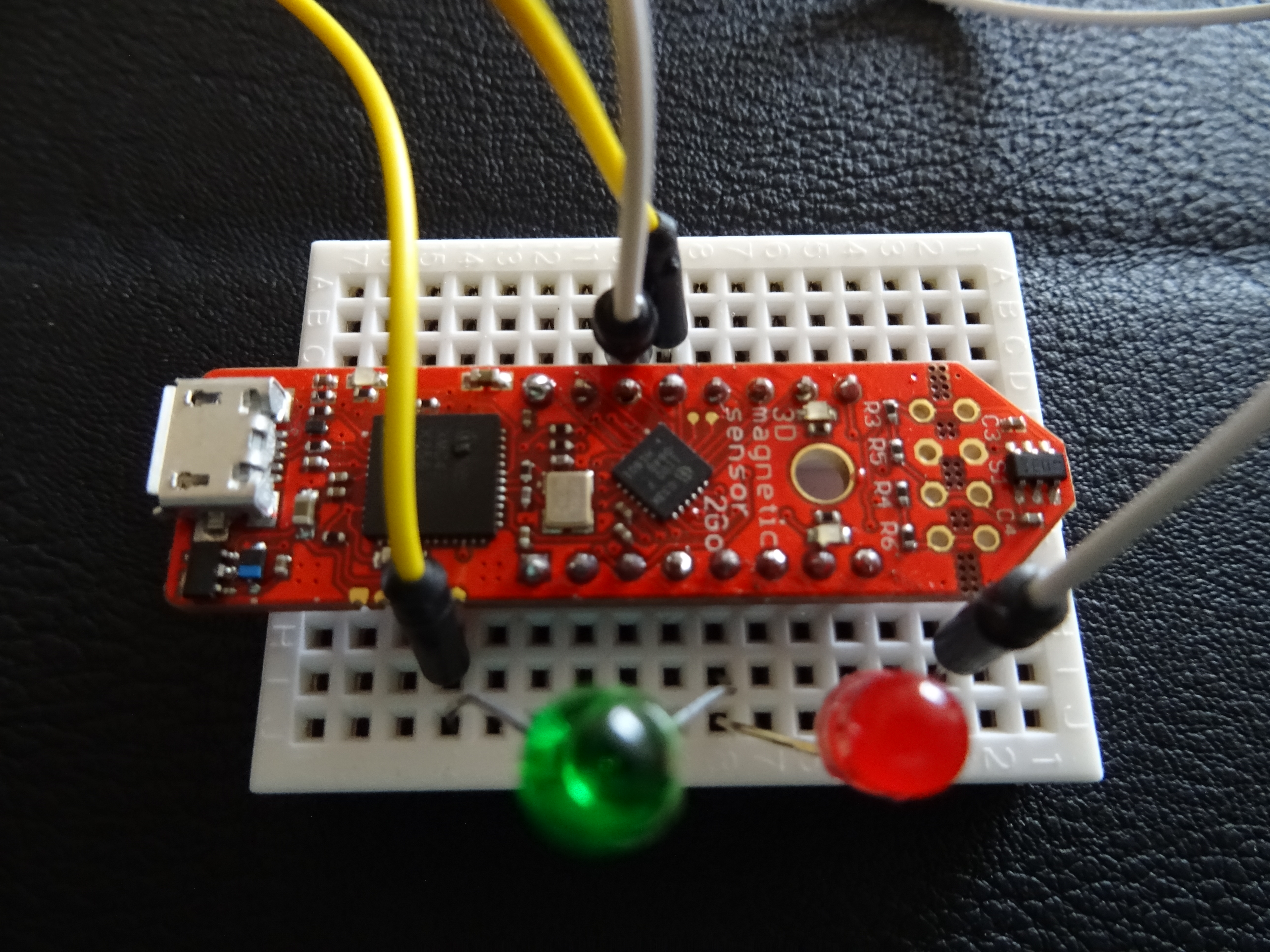
I could see the readings and so all I needed to do now was to attach two LEDS, one green and one red, to the board using pins 4 and 5 and modify the Cartesian script to blink the LED's depending on the readings from the sensor. In the script I decided that I would add all the readings together as I merely wanted to detect the presence of a magnet, and a reading less than one meant no magnet present anything greater indicated there was a magnet. So I wrote a very simple script to take the readings and add them together and blink the correct colour LED depending upon the result.
The next thing I did was solder headers to the TLE493D A2B6. Once that was done I mounted it on a breadboard and connected the LEDS as per the video below. I didn't actually use a resistor partly because I was using a couple of old LED's that I know nothing about in terms of their properties so I just risked them without a resistor and they work fine and as I wasn't intending to run this for longer than the demo I didn't think this posed a risk. However in general all LED's require a resistor to protect them from the full current and I see on the web that possible explosion may ensue if continually running an unprotected LED so be warned always use a resistor to protect the LED. There are plenty of calculators on the net to help you work out what size a particular LED needs.
ConclusionAs you can see, the code for this is very simple, as was the overall project and this was because of the TLE493D A2B6 and it's integration into the Arduino IDE. This means anyone could sit down with this sensor and create a project.


Comments