Presented here is the Guitar Amplifier. The best part of this project is that it is recycled and portable. It is made up of old chocolate box. It is portable and easy to carry. It has various types of facilities. It has volume control to increase or decrease the volume.
Besides a Guitar Amplifier, it can be used as a versatile speaker. Just give the input at the jack with the help of AUX Cable. You can also use it as a speaker. It has a very loud voice, so it is advisable to keep its volume low.
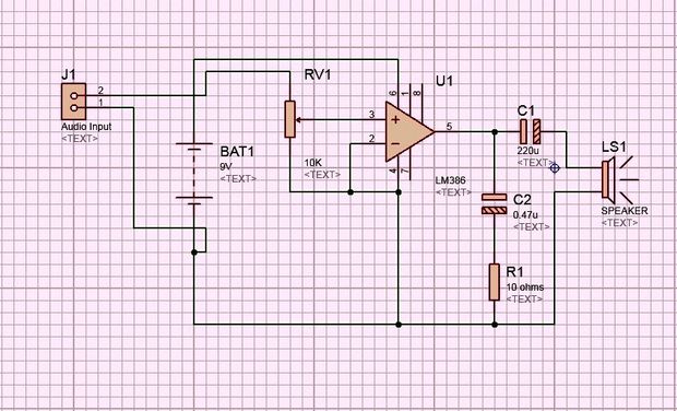
The circuit for this Guitar Amplifier is extremely simple and beginners can also try this out. The circuit is built around LM 386 IC which is very well known in the field of audio circuits.
Step 1: Materials Required- LM 386
- 220uF Capacitor
- 0.47uF Capacitor
- 10 ohm Resistor
- 10k Potentiometer
- 2 pin Coonnector x 2
- 3 pin connector
- 9v Battery
- Battery Snapper
- Case
- Loudspeaker
- Some Tools
- Female Audio Jack
Now, following the circuit diagram we will try to make the circuit on breadboard. Let's get started. First of all, mount LM386 IC on the breadboard. Connect its pin no. 2 and 4 with the help of a wire. Now, attach a 0.47uF capacitor such that its positive terminal connects to pin no. 5 of the IC.
Then connect a 10 ohm resistor across pin no. 4 of the IC and negative terminal of 0.47uF capacitor. Now, connect 220uF capacitor such that its positive terminal connects to pin 5 of the IC. Attach a 2-pin connector for the output of the speaker with one terminal, the negative terminal of 220uF capacitor, and the other connected to pin no. 4 of the IC.
Now, attach a 3-pin connector for the potentiometer. Second terminal of the connector is to be connected to pin no. 3 of the IC. The last terminal (from any side) should be connected to pin 4 of the IC. Now, the power supply is to be given at pin 6 (Positive) and pin no. 4 (Negative) of the IC. A 9 Volt battery is to be connected.
Audio input is available with a 10k potentiometer and pin no. 4 of the IC.
Step 3: Make It on Circuit BoardNow, assemble the components on the circuit board according to the circuit diagram. Here connectors are given for the speaker, potentiometer and audio input.
Wait for the next step till you connect the battery snapper.
Step 4: Holes on BoxMake holes for switch, potentiometer and speaker, then assemble all things in the box.


Comments
Please log in or sign up to comment.