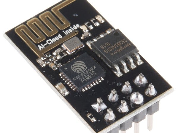
ESP8266 is a 3V WiFi module very popular for its Internet of Things applications. ESP 8266 maximum working Voltage is 3.6V and its very important to note. You must know how to power it, how to serial-connect it with Arduino safely, how to ping and many other things. You should use software like Circuito.io, Tinkercad, Fritzing to simulate and work with the board safely. You should also use Logic Level Controller to use with ESP8266 module.
ESP 8266 PinoutESP8266 has 8 pins, namely:
- RX
- VCC
- GPIO 0
- RESET
- CH_PD
- GPIO 2
- TX
- and GND
VCC and GND are powering pins. RX and TX are used to communicate. You should also look at ESP8266 datasheet at https://cdn.sparkfun.com/datasheets/Wireless/WiFi/ESP8266ModuleV1.pdf
Powering ESP 8266There are many ways to power ESP8266 WiFi module: you can use 2 AA sized batteries for powering, PC port if you have a TTL-Serial-to-USB adapter (Don't try to connect the module to a PC serial port directly, you could cause damage to the module or to your computer!). You can use LIPO batteries to power the ESP Dev Thing board. You can use LM117 3.3V voltage regulator.
The ESP8266’s maximum voltage is 3.6V, so the thing has an onboard 3.3V regulator to deliver a safe, consistent voltage to the IC. That means the ESP8266’s I/O pins also run at 3.3V, you’ll need to Logic Level Controller any 5V signals running into the IC.
Alternatively, if you have an external, regulated supply you’d like to deliver directly to the ESP8266, you can supply that voltage through the 3V3 pin (on the I2C header). While this voltage doesn’t have to be 3.3V, it must be within the range of 1.7-3.6V.
You can also power ESP using two AA batteries. Positive from batteries to VCC of ESP and GND to GND of ESP 8266.
I have used Tinkercad to show how the board can't handle even 0.1 extra. The maximum voltage you can give is 3.5V. You should use such simulation software to look that the power you are delivering to ESP is safe or not.
Using Logic Level ControllerThe level converter is very easy to use. The board needs to be powered from the two voltages sources (high voltage and low voltage) that your system is using. High voltage (5V for example) to the ‘HV’ pin, low voltage (3.3V for example) to ‘LV’, and ground from the system to the ‘GND’ pin.
Communicating ESP 8266 Via Arduino UNOTo communicate with ESP8266 via Arduino UNO you will need a Logic Level Controller in between to safely work with ESP8266.
Connections:For Connecting ESP TO Arduino, Connect ESP8266 RX to Logic Level Controller Level 1.
- Connect ESP TX to Logic Level Controller Level 2.
- ESP VCC to Arduino UNO 3.3V
- Logic Level Controller Level to Arduino 3.3V.
- Logic Level Controller GND To Arduino GND.
- ESP GND to Arduino GND.
- ESP CH_PD To Arduino 5V.
- Logic level Controller HV to Arduino 5V.
- Logic Level Controller HV1 to Arduino 11th pin.
- Logic Level Controller HV2 to Arduino 10th pin.
Test code is given in code section below.
Communicating With ESP 8266 ModuleClick on Start, Run, and type CMD and press enter. Type IPCONFIG and press enter. Type PING and the IP address of your module. A successful PING request will always return a set of numbers. If you get "Request Time Out" messages it means that something isn't communicating.
Then write your IP address to your web browser and now you can communicate with ESP8266 Module.
While In Circuito.ioI use this software to safely run my projects in reality. This software also guides you to wiring and also gives you a test code.
You can find this software in apps section on Hackster.io. Circuito.io gives you choices to build your project. Now you have to add connectivity as ESP8266 WiFi module. You can also add input and outputs.
Click on Add Connectivity and then select ESP8266 WiFi module. Then click on Preview button. You should get Schematic as below.
You can also see its Project Guide. Isn't it useful?


_ztBMuBhMHo.jpg?auto=compress%2Cformat&w=48&h=48&fit=fill&bg=ffffff)


_3u05Tpwasz.png?auto=compress%2Cformat&w=40&h=40&fit=fillmax&bg=fff&dpr=2)
Comments
Please log in or sign up to comment.