

Hardware components | ||||||
| × | 1 | ||||
 |
| × | 2 | |||
 |
| × | 2 | |||
 |
| × | 1 | |||
 |
| × | 1 | |||
 |
| × | 1 | |||
 |
| × | 1 | |||
 |
| × | 4 | |||
 |
| × | 1 | |||
| × | 1 | ||||
 |
| × | 4 | |||
| × | 1 | ||||
 |
| × | 1 | |||
 |
| × | 1 | |||
| × | 1 | ||||
 |
| × | 1 | |||
| × | 1 | ||||
| × | 1 | ||||
| × | 1 | ||||
| × | 1 | ||||
|
| × | 7 | |||
Software apps and online services | ||||||
 |
| |||||
| ||||||
| ||||||
| ||||||
| ||||||
| ||||||
Hand tools and fabrication machines | ||||||
| ||||||
 |
| |||||
The whole idea for this project started when I was looking at an IKEA turntable, which is normally used for Chinese meals:
The idea was simple: why not make this thing turn automatically using a stepper motor and control it with an ARDUINO.
So, I started to 3D print some gears that would fit with a stepper motor that I already had available.
It soon turned out that this construction was not going to work, simply because the stepper motor was not strong enough to move the mass of the wooden turntable.
So I got myself a more powerful stepper motor, a NEMA 17 HS 34:
Although this construction worked (with pain), the stepper motor was barely able to turn the table due to the heavy wooden table and the friction in the plastic gears.
Therefor, I dropped the idea of using the IKEA turntable and 3D printed my own turntable which was much lighter and could easily be turned with the NEMA 17 stepper motor!
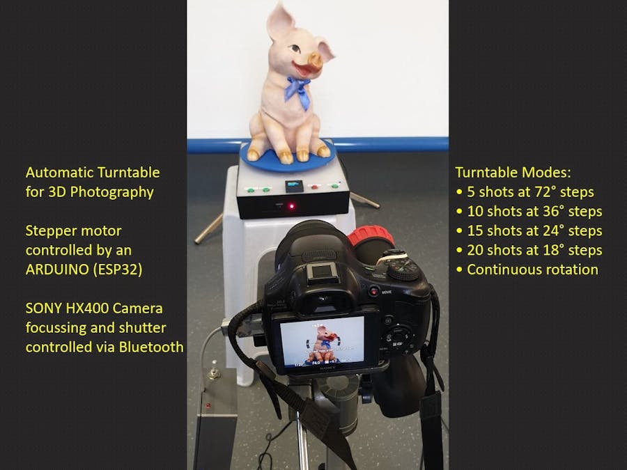
After building everything together this became the final result of this project:
Of course my ambition was more than just make an object turnaround 360 degrees!
I wanted to remotely control my SONY HX400 camera (wirelessly, via Bluetooth) and automatically take a photo every xx degrees. This of course with the aim to convert all the single 2D photographs into a 3D photo and further process the object for 3D printing.
Here you can watch the result: https://youtu.be/ci-9449n2nU
In the following tutorial, you will read how this project has been built.
I wish you good reading, and I hope it is inspiring to build something similar.
ThingsHardware components:
See Step 2 and 3
Common tools & test equipment
Software apps and online services:
- Arduino IDE
- Fusion 360
- CURA
- Autodesk Fusion 360
- ClickCharts Diagram and Flowchart
- EasyEDA
- Fritzing
The Turntable design is shown in the below diagram:
The system, basically consists of 2 main parts:
- The TurntableAssembly (TA) with a ESP32 microcontroller acting as server:
- The CameraControl Box (CCB) with an ESP32 acting as client:
The TA is equipped with an 0, 96 inch OLED display, which together with a pushbutton forms the HMI (human machine interface) for the system:
This HMI enables the user to select the turning modes of the turning table and to monitor the status.
The available turning modes are as follows:
- 5 shots at 72° steps
- 10 shots at 36° steps
- 15 shots at 24° steps
- 20 shots at 18° steps
- Continuous rotation
There are 3 green buttons that are used for actions such as:
- “go-to-Origin” which brings the turntable to a starting position determined by a mechanical switch (built underneath the turntable).
- “Start/Pause” used to restart the set up to initiate another turning mode
- “manual shot” intended to send a shoot command to the camera, but in the current design only used in the process for choosing the turning mode.
All electronics for the MCU as well as stepper motor and its driver are built in the turntable housing.
A blue LED indicates the status of the blue tooth connection to the camera client.
Power is provided with a 12V/3A power supply connected to the mains; a red LED indicates that power is switched on.
The CCB is a 3D printed box, that houses the ESP32, some LED’s (3mm) and a connector to the multiport micro USB plug of the SONY HX 400V camera. Power for the CCB is taken from the camera battery (3, 3V). The CCB also has a connector for a 3, 5mm plug that enables the on/off switching of a separate flood light LED for illuminating the object to be photographed.
The 3 LED’s (apart from the orange power indicator) have the following functions:
- YELLOW LED: indicating that the Camera FOCUS is being activated
- GREEN LED: indicating that the camera is getting the “SHOOT” command
- BLUE LED: indicating the status of the Bluetooth connection with the turntable server.
The following materials are used for the turntable:
The electronic design is shown in the following circuitdiagram. The power supply is 12 V/3A. The internal 5V supply for the ESP32 is taken from the L298N motor driver while the 3, 3 V for the OLED display is taken from the ESP32 board.
Above diagram is made using EasyEDA.
The 0, 96” OLED display has128 * 64 pixels and has been put in a 3D printed housing:
The NEMA 17 Stepper Motor and driver are depicted below:
The Turntable plateau has been designed with Fusion 360 and printed on a Creality CR10S Pro. The borehole is also printed and fits exactly with the spindle of the stepper motor.
The breadboard set up used for testing and building the software with the ARDUINO IDE, is shown inthe following picture:
Note: the 3D printed plastic gear is part of the original construction idea, based on the IKEA turntable.
The assembly of all mechanical and electronic parts is shown in the pictures below:
Note that the whole turntable requires only 1 cable to be connected, namely the 12V power cable. A separate opening is made in the box for (temporarily) connecting the micro USB plug of the ESP32 board, to be used in case of software updates.
The complete building plate has been cut out ofthe IKEA cutting board and made to fit in the ACTION box.
The Software designThe following flowchart shows the high level design of the turntable server software:
In the set up phase a number of Functions are called:
- Set up of the Bluetooth connection
- WELCOME (); //displaying a welcome message until the red button is pushed
- TURNTABLEMODES (); //displaying the possible turntable modes of operation
- HOWTOSET (); //displaying an explanation how toselect the turntable modes
- SETMODE (); //setting the turntable modes by pushing the red button and selecting with the green button
- ORIGIN (); //controlling the turntable to an origin position
The menus, displayed on the 0, 96” OLED display, will appearas follows:
The “LOOP” function itself is pretty short and is listed below:
void loop() {
 CONNECTION();
 switch (turnmode) {
     case 1:                   // Turnmode 1: 5 X 72 dgr)
       STARTandTURN();
       break;
     case 2:                   // Turnmode 2: 10 X 36 dgr)
       STARTandTURN();
       break;
     case 3:                   // Turnmode 3: 15 X 24 dgr)
       STARTandTURN();
       break;
     case 4:                   // Turnmode 4: 20 X 18 dgr)
       STARTandTURN();
       break;
     case 5:                   // Turnmode 5: CONTINUOUS
       STARTCONTINUOUS ();
       break;
                 }
}
The only things, that happen in the loop, are:
· Making the Bluetooth connection
· Running the selected turnmode (as selected during set up)
The complete ARDUINO sketch for the turntable server comprises about 600 lines of code. The complete listing is included as part of this tutorial, the ARDUINO code is provided with an ample amount of comments.
Step3: Making the Camera clientThings usedThe following materials are used for the turntable:
The power supply 3.3 V is directly taken from the Camera and converted into 5V, needed for the supply of the ESP32 (which internally generates 3.3V)
The Fritzing diagram looks as follows:
Nothing better than a good circuit diagram:
The Sony DSC HX400V Camera has a USB connector that looks like an ordinary micro USB connector (female) with 5 Pins and indeed a normal micro USB male connector can be plugged in for 5V charging and data transfer (see table below):
In fact the Sony connector is what Sony calls “a Multi/Micro USB Terminal that Supports Micro USB compatible device”, with 10 additional pins, that can be used for remote control of the camera.
In this project only the following pins of the multiport connector are used:
On the Internet, I found 3 sources for buying the relevant Multiport connector:
https://www.studio1productions.com/parts/sony-multiport-connector.htm
On the website of Studio1 you can also find more details on the Pin out of the multiport connector.
I bought mine from the Slovenian company MobileExcopter, who had the cheapest shipment option (EU mail).
I used a 4-wire telephone cable for connecting the connector to the ESP32. The soldering of the wires to the connector is a tedious job, as you can see below, especially pin 10 for the 3.3V connection.
I later found that they also have a better version where also pins 1 and 10 are easier connectable.
During the design of the Bluetooth Client for the Sony HX400V Camera it turned out that the 3.3V supply from the camera was insufficient to feed the ESP32 NodeMCU module. For this reason a step up convertor had to be used, whereby the 3.3V from the camera is converted to 5V as used by the ESP32. I added a power switch and an orange LED to indicate that the USB connection is made and the camera switched on.
As can be seen in the electrical design above, two 4N35 Optocouplers have been used to isolate the client from the camera. Sending a HIGH value from the GPIO pins of the ESP, brings the Focus or Shutter contacts of the camera to LOW, which results in activating the focus of the camera or the shutter.
I made a 3D printed casing for the connector to the ESP32:
The assembly of all mechanical and electronic parts is shown in below pictures:
The software for the Camera Client mainly consists of the code related to making the Bluetooth connection and receiving command data.
If there is no Bluetooth connection, the blue LED will blink until a connection is made.
If a connection with the server has been established, the shoot command received will result in a sequence whereby:
1. The LED floodlight will be lit
2. The yellow LED will be lit and the related optocoupler will bring the focus line of the camera to LOW
3. After 1 second the green LED will be lit (while the yellow LED goes off), thus bringing the shutter line of the camera to LOW via the related optocoupler
4. The LED floodlight is switched off
The complete sequence takes just 1, 2 seconds, which is tuned to the holding time of the turntable which is 3 seconds.
The complete ARDUINO sketch is almost 200 LOC, so not very long.
The set up for the LED floodlightAs can be seen in the circuit diagram for the Camera Client, there is a direct output from the ESP32 (GPIO14) to a relay that I built into a cheap Floodlight bought at the local ACTION store:
Note: that the module stated in the diagram is not the one used (it just shows the principle), but instead, the one below is used.
Since both the relay and the LED lamp operate a 5V, a simple 5V 2A charger can be used to power this set up.
The relay unit used is a 5 V type that can be triggered with the LOW output of a ESP 32 GPIO pin (GPIO 14 is used in this project). The 3, 3 V HIGH output is not suitable for triggering this device, so the yellow selector has to be set at low level trigger.
The relay unit has an optocoupler on board which enables direct connection to the GPIO pin.
The cable used for connecting the Camera Client box to theLED Floodlight is a cheap audio cable also from the local ACTION store.
Concerning 3D Photography you will find many descriptions and instructions on the internet on how to do this, e.g.:
Or:
Or:
There are various (free or paid) software packages available that enable conversion from a number of 2D photos into one 3D object.
Once a good 3D object has been created, it can be converted into code (with a slicer program such as CURA), that can be applied on a 3D printer to reproduce the original model.
To make a 3D model from several 2D pictures, there are a number of recommendations that will help in making a successful copy :
- A number of shots of the model are needed all around 360 degrees
- At least 3different angles to the model are needed, bottom, middle and top
- With the turntable set at 10 shots per 360 degrees and 3 elevation angles this leads to a number of 30 pictures
- Important is the use of a plain background as well as good illumination of the model
- Put the camera on a tripod and level it horizontally
- Make sure all images have the same dimensions and are taken from the same distance with the same zoom factor.
- Save the images in a sequential order and numbering in *jpg format.
After some experimenting I finally got a very nice result using the below setup:
A beautiful 3D picture was created out of 72 separate photographs taken with a Sony HX400V camera connected to the automatic turntable:
After sending these photographs to Autodesk ReCap Photo, I got this very nice result:
Importing the 3D object in to CURA and printing it on my Creality CR10 S Pro 3D printer, these are the resulting 3D printed baby copies next to their original:
This was quite a big ARDUINO project, it was time consuming, but fun making it, especially when at the end it was possible to reproduce a 3D object on my 3D printer, using this DIY turntable.
The Bluetooth connection was mainly included for learning and experimenting reasons. Of course it is possible to make the whole project with just one ESP32 or even an Arduino UNO, with a cable directly connected to the Camera. This will of course simplify the project, but at the cost of a cable that limits your movements to some extent.
Have fun reading and/or making your own Turntable!


_t9PF3orMPd.png?auto=compress%2Cformat&w=40&h=40&fit=fillmax&bg=fff&dpr=2)


_3u05Tpwasz.png?auto=compress%2Cformat&w=40&h=40&fit=fillmax&bg=fff&dpr=2)
Comments