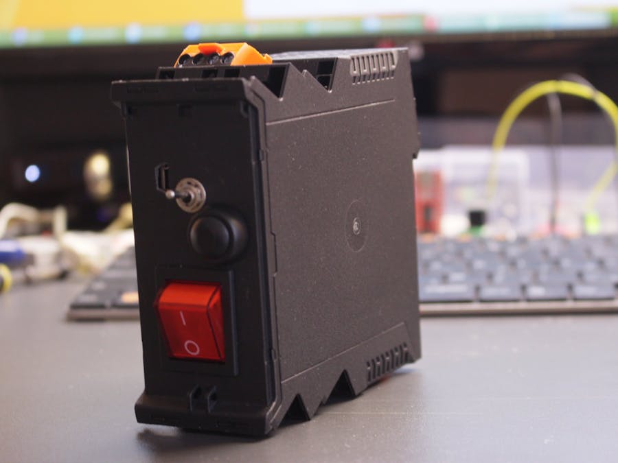
Continuing the series of Cube(s) for Greenhouse (Climate Cube for Greenhouse, IoT Cube for Greenhouse) it is time now to place some safety stuff around.
The PastSince we use lots of electric things (for example high pressure water pump, solenoid valves, electric valves, etc.) for production of green pepper, in every single year it happens when suddenly the water pipe line stops serving water. Of course it usually stops mid summer, mid day when irrigation is the most needed. It would not be a problem if we were using real soil for production. But we use coir based growing mediums and those have only a few hours of water buffer effects. Meaning one day without irrigation can end the session or turns plant growing into generative way. So somehow we should know when the stop happens to know how many water we have to replace later.
The PresentIn the picture above you can see the central irrigation system. Above through that 63mm wide PE pipe we get the water for irrigation. In this pipe the standard pressure is around 6 bars. When service of water stops, pressure lowers in the pipe so putting around it a pressure switch can signal me (picture below).
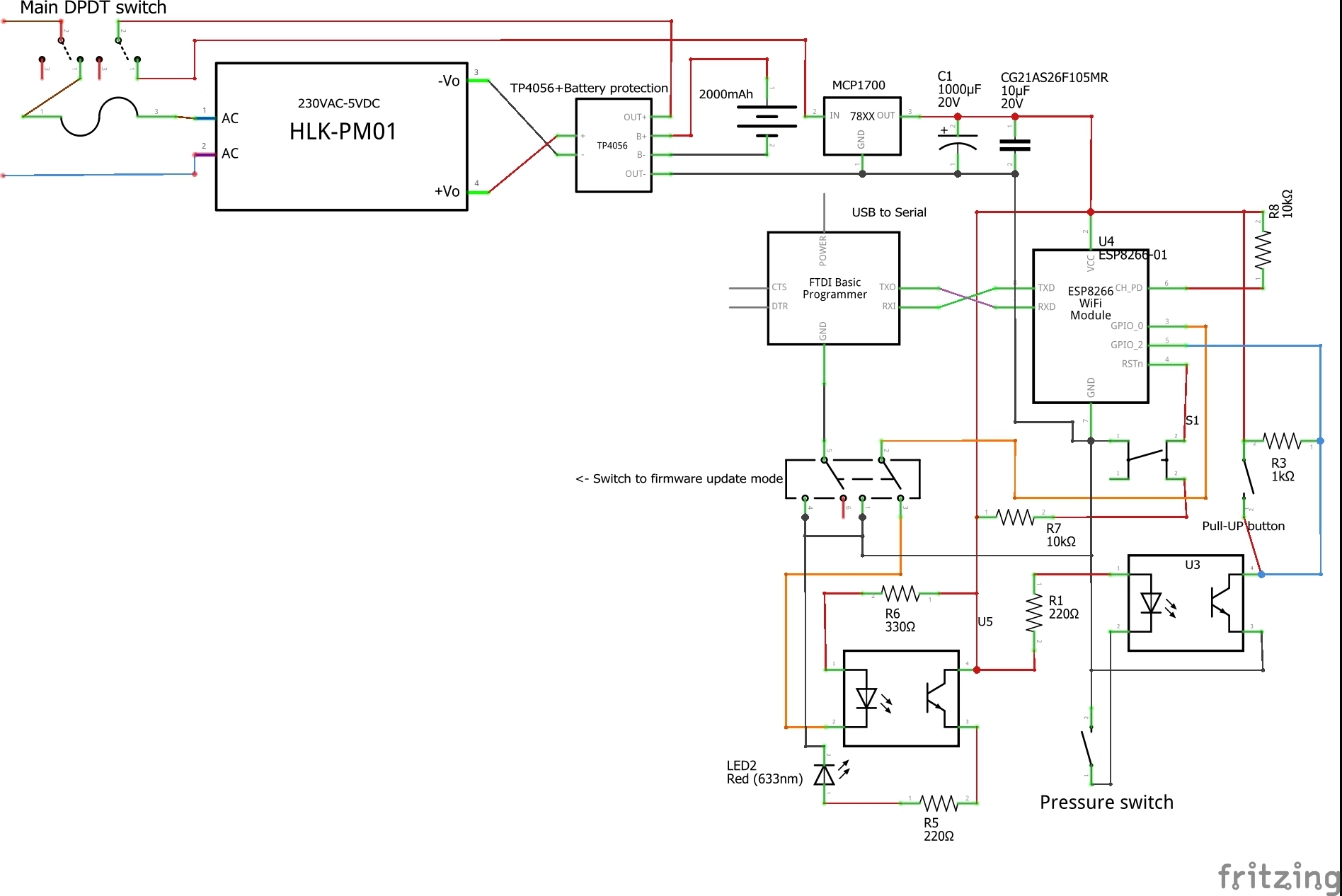
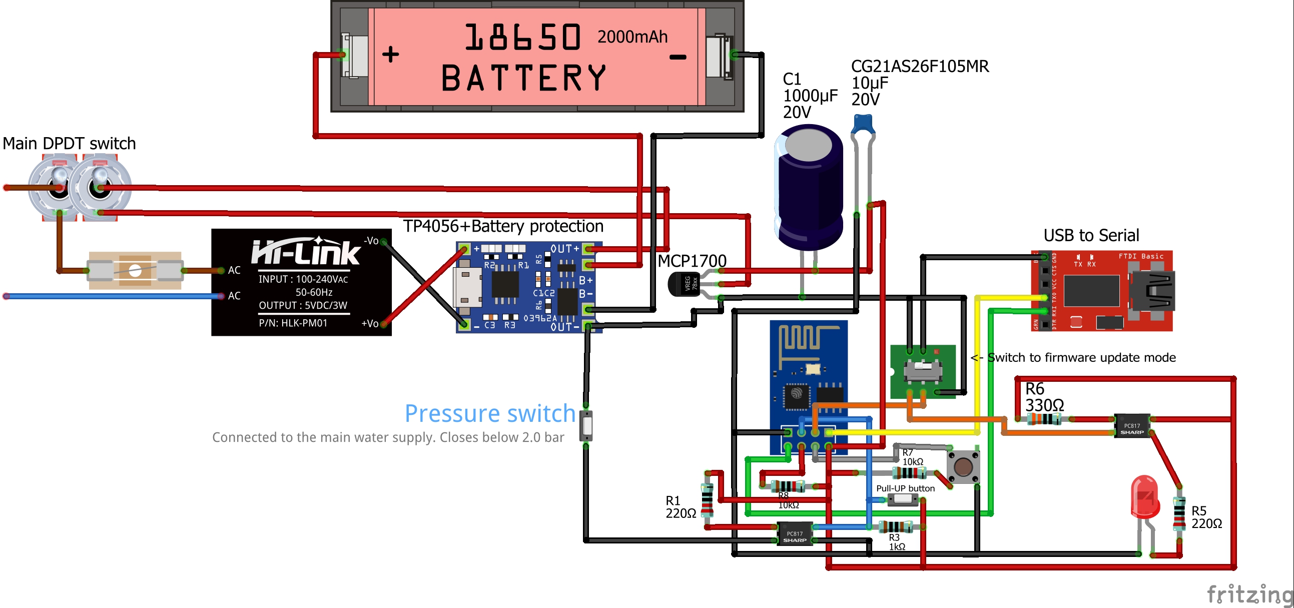
I put the Alarm Cube into the metal box of the irrigation system. The wires from the pressure switch closes a 24VAC coil of a relay. This relay has an NO (normally open) state end which closes a circuit going into the Alarm Cube via an optocoupler (see the below picture for circuit details):
To 'visualise' the current condition of water pressure a red LED just connected to the GPIO 0 pin of the esp. It will blink rapidly if no water available and can be recognised by someone who just simply passes by :).
To communicate with PC using USB there is a need for the FTDI chip based board. If you look at the wiring diagram you can see that i put a dpdt type switch. It switches between the two states of normal RUN mode and firmware UPDATE mode. (ESP8266 details about pin outs). Plus this switch not only pulls pins into the needed state but disconnects ground of the uart board.
Little sidetrack. (There is a step-by-step process on how to upgrade firmware and debug it later. Switch off Alarm Cube then switch into upgrade mode where (as can be seen on diagram) GPIO 00 gets low state and uart board gets its ground connected. Connect USB cable,switch on the Cube, do the upgrade and switch off. Then you switch back to normal RUN mode, power the CUBE, and after then switch back into upgrade mode so the uart board become a part of the circuit and you can debug through USB.)
Battery Powered Alarm CubeHesitated a few days to use battery for this project but in the end I decided to lets have one. Actually there could be many reasons stopping central water service and what if the one is when there is no electricity.
The tricky part was the LDO vreg. itself. The MICROCHIP has many types like the MCP1701 and ..03. Analog Devices also have many types like the ADP122 but it has not got that prefboard friendly TO-92 socket... Lets shorten the story, with the MCP1700 and that 2000 mAh battery and charger/batt. protection board the Alarm Cube can operate one day connected to IoT Cube and doing continuous uploadings. That is far enough for me and was a hard test.
The Code Running on the Alarm CubeBasically it is so simple that it only deserves one sentence. When water service (or mains) stops the GPIO 02 gets into LOW state and the program loop starts to blinking the LED and connects to the IoT Cube wifi network sending thingspeak channel a 1 value which then will be used by a thingspeak phone app to send an alarm signal to my ears when... sunbathing at a beach. :)
More to Come...Next Cube project for Greenhouse going to be the Weight Cube for Greenhouse where... :)


_3u05Tpwasz.png?auto=compress%2Cformat&w=40&h=40&fit=fillmax&bg=fff&dpr=2)
Comments
Please log in or sign up to comment.