


Hardware components | ||||||
 |
| × | 1 | |||
 |
| × | 1 | |||
| × | 1 | ||||
 |
| × | 1 | |||
* Or any SBC supported in Maker.MakeCode
Part 2 (of 4): Displaying cards on a screen.There are nine sections in Part 2 of the project::
- 1 = Introduction
- 2 = Planning how we use the available pixels
- 3 = Drawing the border of the card
- 4 = Testing (1)
- 5 = Using persistent memory for enhanced graphics
- 6 = Drawing bitmaps onto the cards
- 7 = Testing (2)
- 8 = The card-game engine
- 9 = Next steps
----------------------------------
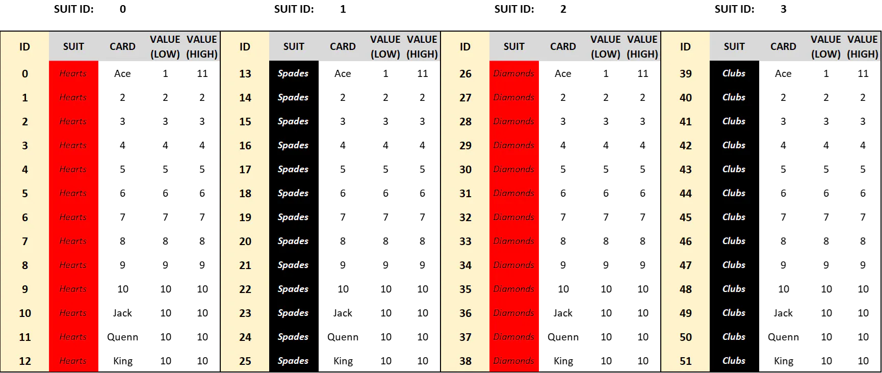
1: IntroductionIn Part 1 of this project we set up a virtual packs of cards and built some related functions which allowed us to deal a hand of cards to a virtual player. We went on to build some simple code to display the playing cards on the micro:bit 5x5 LED matrix (e.g. "AH" represented the Ace of Hearts and "5C" the Five of Clubs).
It is possible to extend the display code we wrote in Part 1 and use the micro:bit LEDs as our screen for the game. BUT scrolling "KH AC 3H 2S TC" does not make for compelling game-play, and it is a stated goal of this project to make a game that is fun to play. The micro:bit native display is just not viable to emulate how someone plays cards.
Typically a person playing a game of cards has a hand of several cards in their possession, and they are able to look at all their cards simultaneously... the act of scrutinising ones cards is a visceral and key part of the game dynamic. Like chalking one's cue while playing snooker.
A more robust display is necessary.
Luckily there are lots of great display add-ons for micro:bit that are adequate. For this project I am using a SSD1306 - a standard peripheral that many of the great micro:bit manufacturers support. It has a resolution of 128x64 pixels which, as you will see, is just about adequate to show a hand of 5 cards and some game-play info.
Specifically I am using the XinaBox version of the SSD1306 - the OD01 - for the following reasons:
- They all work the same, so one SSD1306 is as good as the next.
- I am COO at XinaBox, But you can use any SSD1306!
- I also need to use the IM01 micro:bit bridge from XinaBox - it provides microSD card support, on which we store image info that is used to enrich our visual displays.
- The OD01 connects easily to the IM01 bridge. I don't like soldering or using cables, if it can be avoided :)
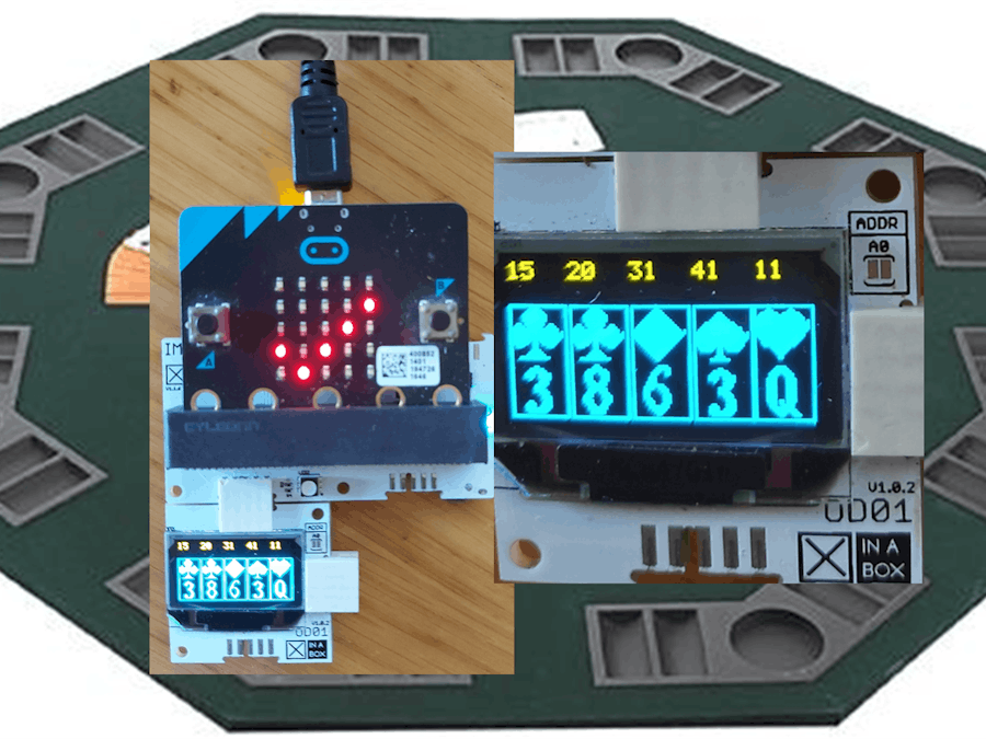
The rig I use looks like this:
NB - if you use a different SSD1306 then you should be able to adapt the code quite easily. If you are using a completely different display then the code will need to be adapted accordingly... but you CAN use the same overall architecture... as you will see, the code is written such that you ONLY have to make significant changes to 1 function to write to your specific display (the function drawAsset())
If you are using the XinaBox OD01 then remember to import the extension into MakeCode: type in OD01 (or "xinabox/pxt-od01") in the import extensions window.
2: Planning how we use the available pixelsWe have 128x64 pixels to play with:
With this space we need to be able to display the following:
- Up to five cards together on screen. Note - five is a bit arbitrary and may not be enough for some games. But space is very limited and five is the upper limit on how many cards can comfortably be shown on an SSD1306. For Blackjack we never need to show more than 5 cards simultaneously
- We need to show some game-play messages: For Blackjack we'll need to show score and bet (at least)... of course the messages we show will be determined by the game we are designing. With this in mind we'll allocate some space (the top 2 lines of the screen) for in-game messages, but we'll keep them generic in this part of the project.
To fit 5 cards on the screen we need to optimise every available pixel:
- The screen is 128 pixels wide. 128 / 5 = 25 remainder 3. So, if we allocate 24 pixels width to each card we could show 5 of them together, with a gap in between. BUT - we can only insert the gap between 3 of the cards, so we are going to have to bunch up the last 2! Oh for just 1 more pixel ;)
- The screen is 64 pixels high and can show 8 lines of text (using the built-in font). One line of text = 8 pixels. The top part of the OLED we are using is orange - enough for 2 lines of text (16 pixels). The cards are 24 pixels wide so lets make them 48 pixels high - that leaves exactly 16 pixels at the top for 2 lines of text messages. The dimensions of each card are shown below:
With the space available we are going to draw cards that look like this:
The visual component of each card is composed of 3 elements:
- 1 = Border
- 2 = Suit
- 3 = Face
We are going to draw each of these elements separately. Also note the following:
- We will draw a border around each of the cards that is 1 pixel wide.
- A card is 24 pixels wide and 46 pixels high.
- All cards will be drawn at height = 17 pixels.
- The x-value will vary - each card is drawn adjacent to the previous card, with a 1 pixel gap between borders.
We'll use the space we have available to draw the components of our cards as shown in the image below:
For each card in a players hand we need to draw these 3 components, and we need to draw them in coordinated locations on the page..
The function drawCard() pretty much writes itself (or so I thought *):
* An interesting bug creeps in if you try to draw the border first, which is what I did. I found through testing that on some occasions the suit and face of a card is not drawn if we try draw the border first. The bug cannot be replicated with the ordering above and visually it works fine.
We pass in lateralPosition to identify where to draw the card, and cardID so that the right card is drawn.
This function is the crux of this part of the project - if we can get it right then all we need to do is calculate where to draw the card on our screen, pass that into this function and it will do the rest. We'll be able to use this function in any card game, and adapt it for any display.
In the following sections we'll look at each of the graphical elements in turn. We start with the card borders:
3: Drawing the border of the cardIf you are using an SSD1306 then find a MakeCode library for it that provides you with some way to draw a straight line. You might even get lucky and have access to a drawRectangle function.
We need to draw four straight lines that form a closed rectangle, and we know exactly how many pixels wide and high the rectangle needs to be. The value lateralPosition will tell us the x-coordinate where we need to draw this rectangle - we know the y-coordinate (y=16, which is pixel 17 from the top cos the numbering starts at 0):
The variable lateralPosition can only take on 5 values:
- Card 0 is drawn at x = 0. The length of the card is 24 pixels, then we'll leave a gap of 1 pixel, then Card 1 is drawn in the next position, at pixel 26. So, we shift 26 pixels to the right each time we draw a new card:
- Card 1 is drawn at x = 26 = 1*26
- Card 2 is drawn at x = 52 = 2*26
- Card 3 is drawn at x = 78 = 3*26
- Card 4 is drawn at x = 103 = 4*26 - 1. We have to do this, otherwise the right-hand border of the final card is drawn beyond the edge of the screen.
lateralPosition is therefore determined by which card we are drawing. To make life easy we'll create a function called getLateralPosition which we will pass a value (0, 1, 2, 3 or 4) and which will return the position at which to begin drawing the card. The nasty-little issue of having 1-too-few pixels and needing to squash up the last 2 cards is taken care of in this function too:
It is preferable to test code as you develop it, rather than wait until the end, so lets update the testing function we built in Part 1 to use the drawCard() function and take advantage of the OD01 display. Change the Button-A press function as shown:
When the A button is pressed, the OD01 display is cleared and drawCard() will try to draw all 5 cards that are part of the 5 element playerHand array (so far we have only programmed it to draw the borders of the cards of course). We are also showing the IntID of the card above it at the top. The B-button is unchanged for now (although you can adapt that too if you like).
Compile and run the program and test that the borders of the card are being drawn correctly.
As we add the other components - suit and face - we will be able to test them using this function without any further modification.
Crufts: a cruft is code that serves no purpose, and as a program grows so too does the likelihood of crufts creeping in. In Part 1 we developed some functions that we used for testing - these functions converted the integer value (0-51) into a 2 character string to represent the card. We don't need this code any more - it served its purpose but now that we are using the OLED display for output we don't need functions that were designed to output succinct strings to the micro:bit 5x5 LED matrix. So, I have deleted the following 3 functions from Part 1:
- getCardStr()
- getSuitStr()
- getFaceStr()
I have a secret weapon at my disposal in making this game - access to persistent memory on a microSD card. The IM01 bridge that I use to connect the OD01 to the micro:bit has a mount for a microSD card, and a MakeCode library that allows us to read and write to it :)
- The value to me of this is that I can store image data on a microSD memory card, which I can read during runtime.
- 22x22 = 484. We can represent a 22x22 monochrome image using a string of ones and zeroes that has 484 characters ("100101001010101... etc").
- I designed 17 tiny bitmaps, 22x22 pixels, that were tailored to the available space. One bitmap for each of the four suits, and one for each of the 13 faces.
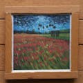
- The bitmaps are stored as.txt files and are small enough to read into micro:bit memory, which makes it possible to draw them on the SSD1306 display (using a very simple technique, which we will look at later). Here's a screen-grab of one of them:
- I won't go into detail about how I built these - that might be worth a separate project by itself. Suffice to say good old Excel was at the heart of it:
I used a free online image editing tool whose name I can't remember (sorry) to convert B&W images into 22x22 bitmaps. I opened and edited these in Excel then converted them into strings of the form "011001011001 etc", which is what we need.
- The micro:bit memory is very small, but the bitmaps were smaller - 484 characters ("1001010001 etc")... a viable size to load one into micro:bit RAM to work with. But too big to preload as constants, so persistent memory was necessary.
The full set of bitmaps that I used is available here. If you plan to complete Part 2 you will need to download these and add them to a microSD card... format it to FAT32 and save all the files into a folder called "im01".
There are 17 bitmaps, which we refer to as the cardAsset bitmaps:
FACE:
- face0.txt = Ace
- face1.txt = Two
- face2.txt = Three...
- ... face12.txt = King
SUIT:
- suit0.txt = Hearts
- suit1.txt = Clubs
- suit2.txt = Diamonds
- suit3.txt = Spades
To use the microSD capabilities of the IM01 bridge you need to import an extension into MakeCode. Go to the MakeCode extensions screen and type in the following: xinabox/pxt-im01.
Note: If you are using the new micro:bit 2.0 then the additional memory available should be enough to pre-load the bitmaps as constant strings... I haven't tested it, but the bitmaps only take about 16k of memory, so it should be fine. The onscreen images will draw more quickly if the bitmaps are in RAM.6: Drawing bitmaps onto the cards
The library that we use for the OD01 display provides us with a function that we can use to draw individual pixels, The SSD1306 you are using should be supported by a library that has a similar function:
The screen itself is 'monochrome' - only 1 colour. We can turn pixels on (color = 1) or off (color = 0).
We will load bitmaps into memory then draw them onto a 22x22 space on the OLED display. The location that we need to draw each bitmap will depend on whether we are drawing Suit or Face. So we need a function that will draw a 22x22 bitmap at a location on the screen that we pass in. We will use the same function to draw Suit and Face (or any other bitmap we might want to draw):
NB: If you are using a different display - either a different SSD1306 or a completely different output - this is the ONLY function you should need to make substantive changes to (and maybe just the 1 line in black above, if you are using the supplied bitmaps).
We use this function to draw both the suit and the face, but we don't call it directly. We know that the cardAsset images are 22x22, so we can pass them in to the generic drawAsset() function using the following drawCardAsset() function:
The reason I have separated drawCardAsset() from drawAsset() is that drawCardAsset() ALWAYS and ONLY draws the Face and Suit 22x22 pixel images. I might want to draw a few other images, e.g. a splash page, and I don't want to mandate that the images I use for that are always 22x22... drawAsset() is flexible enough to manage images of other dimensions. The only restriction is that we need to know the dimensions of the image when we write our code... not ideal, but workable and its like that to take pressure off the limited processing power of the micro:bit..
We can now complete this suite of functions by finalising the drawSuit() and drawFace() functions we first saw in Section 2:
The IM01 read file function is used to read the contents of the cardAsset bitmap files into micro:bit memory. We use the join function to create the file name that we saved the bitmap as (e.g. face10.txt or suit3.text).
7: Testing (2)When you click the A-button the function that we adapted in Section 3 should now result in playerHand being displayed as visually recognisable playing cards. Five cards should print on the screen, from left to right and they should all fit nicely.
Adapt the code to test some of the other parameters we use in our code. Check the logic and try to break it.
If you have issues always check the microSD card:
- Ensure you have a microSD card inserted into the IM01.
- The microSD should have been formatted to FAT32
- The bitmaps from Sections 5 and 6 should be saved on the microSD card in a folder called "im01".
Run the program and test the code until you are satisfied that it is working correctly, You would have tested the shuffling and dealing in Part 1, but verify all of that is still working while checking that...
- Five cards are being dealt per hand.
- They are displayed correctly and clearly
Note: the duration it takes for the images to load will depend a bit on your microSD card. Its quite quick at this stage, not instantaneous, but in the real world the process of dealing does take time, and the speed with which the cards are drawn could be said to emulate this. FYI I don't know how to double-buffer onto an SSD1306 in MakeCode :(8: The card-game engine
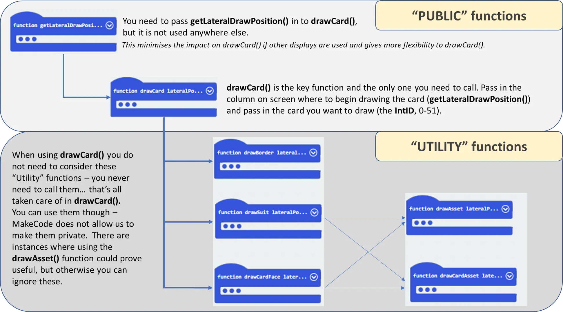
We have built a very simple and pared down "card-game engine". What this means is that we have a set of 'public' functions that we can call in a program we write that will help us build a card game easily. I am going to call this the PragmaticCardCore Engine (PCC engine). Pragmatic cos we'll make it up as we go along :)
In Part 3 we will look at how to use it. The context will be building blackjack, but the theme will be how to use the 'public' functions built here.
This really doesn't need to be limited to micro:bit at all. The excellent Maker.Makecode platform from Microsoft supports a broad range of microprocessors and has the same block coding interface as I've used to build PCC, so it can be easily adapted for multiple platforms.
The image below sums up what we've done here:
The full project thus far is available as a shared MakeCode project.
9: Next Steps:If you've got this far and everything is working for you then you have a solid foundation on which to build a card game. Go for it!
In Part 3: Implementing Blackjack I will show you how to code up blackjack by building on the base we have already established. But at this point please start thinking about the card games you enjoy... perhaps not all will be possible given the restrictions of the micro:bit and the display, but there's plenty that are, including a few fun solitaire games. If you are able to build something else on top of Part 1 and Part 2 please get in touch and let me know :)
-------------------
Thanks for reading and please check out Part 3 (or Part 1, if you haven't already)
This project is meant to be easy to read and relatively simple to implement. It shows you how to achieve a useful outcome without labouring on irrelevant technical details. If you like this style please check out my book: Beginning Data Science, IoT and AI Using Single Board Computers.
Guide to 'public' functions


Comments
Please log in or sign up to comment.