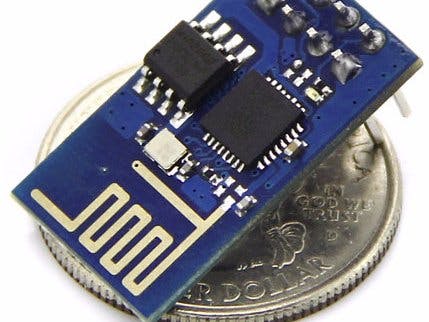
In this tutorial we use an Esp8266 ESP-01 chip which is really cheap yet really effective while communicating over the internet. Refer my previous tutorial to see how to get started with the ESP-01 Wi-Fi module, configure it, and verify that there is communication established between the module and another device without using a USB to TTL converter . ESP8266 Baisics.
In this tutorial we are using an USB to TTL converter to program the Esp8266 ESP-01 . Here we can use Arduino IDE to develop the web server to control an led remotely.
Hardware SetupWe can either use a usb to ttl converter or use an arduino to program the the Esp8266. Refer the following diagram and set up the hardware accordingly. Here there are three methods you can follow one which suits you the most.
USB to TTL Converter with DTR PINIf your using an usb to ttl converter which has an DTR pin then uploading will go smoothly. Please be informed that Serial monitor will not work anymore.
USB TTL------ ESP8266 ESP-01
GND-----------GND
TX--------------RX
RX--------------TX
RTS------------RST
DTR-----------GPIO0
USB to TTL Converter Without DTR PINFor USB TO TTL converter without DTR pin we have to use manual flashing .For this we must use two push buttons. Refer the following diagram
USB TTL---------------- ESP8266 ESP-01
GND-----------------------GND
TX---------------------------RX
RX---------------------------TX
Reset Button------------RST
Flash Button------------GPIO0
While uploading the code press flash button, keep the flash button pushed while you once click on reset. You may now release the flash button. The ESP8266 is now in flash mode. You are able to upload the sketch.
Using Arduino Uno to Flash the code to ESP8266You can use arduino uno for flashing code to ESP8266 ESP-01 .
Arduino---------------- ESP8266 ESP-01
GND-----------------------GND
TX---------------------------TX
RX---------------------------RX
Reset Button------------RST
Flash Button------------GPIO0
While uploading the code follow the same procedure to keep the flash button pushed while you once click on reset. and release the flash button.
UploadingUse any of the above suitable method and now open the Arduino IDE and select choose your ESP8266 board from Tools > Board > Generic ESP8266 Module
Now copy the below given code to Arduino IDE and press upload button. Change ssid into your wifi accesspoint, and change the password into yours. and compile.
Open the serial monitor and open the URL shown in your serial monitor
Open the URL and and connect the GPIO 2 of ESP8266 to longer lead of led. Now you can control the Led remotely by using the internet.
Remove all the wires which were required for uploading .Lm117 is used to provide regulated 3.3 output.
Comments and Questions welcome! Thanks for reading.


_ztBMuBhMHo.jpg?auto=compress%2Cformat&w=48&h=48&fit=fill&bg=ffffff)


_3u05Tpwasz.png?auto=compress%2Cformat&w=40&h=40&fit=fillmax&bg=fff&dpr=2)
Comments
Please log in or sign up to comment.