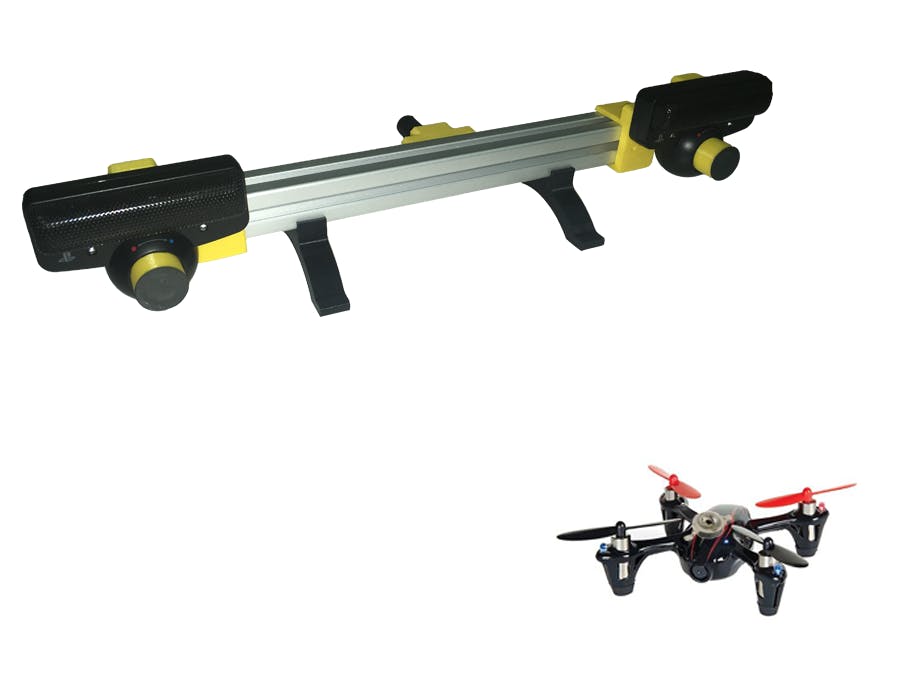
The story began four years ago when I decided to implement a position controller for my mini quadcopter. Back then, I needed to measure the position of my quadcopter and use that measurement in a PID feedback loop. Later, when I joined the ARAS robotic group for my masters, I encountered this problem once again when I wanted to control the end-effector position of a cable-driven parallel robot. Ideally, we have access to commercial systems like Vicon through which we would be able to get these measurements. These systems use multiple synchronized IR sensitive cameras to observe the tracked object on which we have some IR reflective markers. Next, the pixel positions of these markers are translated into the pose estimates. However, these systems are costly and often hard to obtain.
Thus, I decided to build my little pose tracker system. This system is comprised of two off-the-shelf PS3eye cameras mounted on an aluminum profile through some 3D-printed components. In the following picture, you can see these 3D-printed components along with the aluminum profile:
There are two primary modifications that I made to these cameras to make them suitable for this project. First is the addition of synchronizer IOs, and the second is removing the lens and changing it with a night vision CCTV lens. The former modification is for synchronizing the two cameras together, and the later is for making the cameras sensitive to the light coming from the IR LED, which we use as our active marker. In the following pictures, you can see these modifications:
When we connect the sync signals, the frame capturing of the two cameras happen at the same time:
In the next step, I attached a filter made out of an old floppy disk in front of the camera. The notable property of the material used in these disks is that they filter out visible light while they pass IR wavelengths.
The captured image with this filter is a black background with a shiny bright dot at the location of the LED. This simple image makes the task of tracking extremely easy. In the software, I threshold the images and calculate the geometrical center of the white pixels. This center points correspond to the center of the LED in the image.
When we use a camera as a metric measurement device, we have to know some specific parameters of the camera. Parameters such as lens distortion, intrinsic parameters, rectification, and projection matrices. To estimate these parameters, we need to perform a calibration procedure. Here, I used the ROS Image pipeline package to do this. You can find the detailed procedure of calibrating a stereo camera in Here. The only thing we need is to have ROS installed on the system and publish the images from the two cameras. For publishing the images, I created a simple node that reads from the two cameras using python openCV and publishes the frames in the form of ROS image messages. This node is called stereo_image_publisher_node. In the python code for this node, we must set the left and right camera numbers ( the index of videox devices in the /dev directory):
left_camera=1
right_camera=0
Having this we follow the camera calibration procedure whose results are two .yaml files for the left and right cameras. We should replace the old YAML files in the stereo_image_publisher_node/scripts directory with these new ones.
The SoftwareSo far, we have built our hardware, and we are now ready to move on to the software part. We want to processes the LED pixel positions in the two images and using them, calculate the 3D position of the marker in the world. In my blog, I have explained the technical procedure of doing so in detail( To be added). Here though, I only give a brief overview of the process. First, we extract the LED locations from the images. Then using the camera distortion parameters, we undistort the pixel locations using the OpenCV UndistortPoints function. Next, having these undistorted values and the camera projection matrices, we can triangulate the 3D position of the marker point in the camera coordinate using the OpenCV triangulatePoints function. This procedure is carried out in the ir-tracker-node-3D. After finding the 3D location of the marker point, we publish the result in the form of TF markers and geometry_msgs/Pose messages. In the following video, you can see that the system can track the IR marker with respect to the camera coordinate frame. Here you can see the visualization in the ROS rviz.
The source codes for this project can be found at our GitHub repository.


Comments
Please log in or sign up to comment.