


Hardware components | ||||||
 |
| × | 1 | |||
 |
| × | 1 | |||
 |
| × | 1 | |||
Software apps and online services | ||||||
 |
| |||||
The hands-free thermometer is really a good device to check for one temperature without someone holding a gun to your face. This device can be used to check the temperature in both degrees Celsius and degrees Fahrenheit. So it's comfortable for people who would prefer anyone one of those. I would be honest with you guys this project was made in the month of July 2020, due to some issue I couldn't post about the project. So now let's dig deep into this project.
COMPONENTS- Arduino pro mini 5V
- MLX90614 (non-contact temperature sensor)
- 5V buzzer
- Oled 1.3 inches I2C
- RGB led
- Push type button
- 2n2222 transistor x2
- 1n4007 diode
- 100uF capacitor
- Few resistors
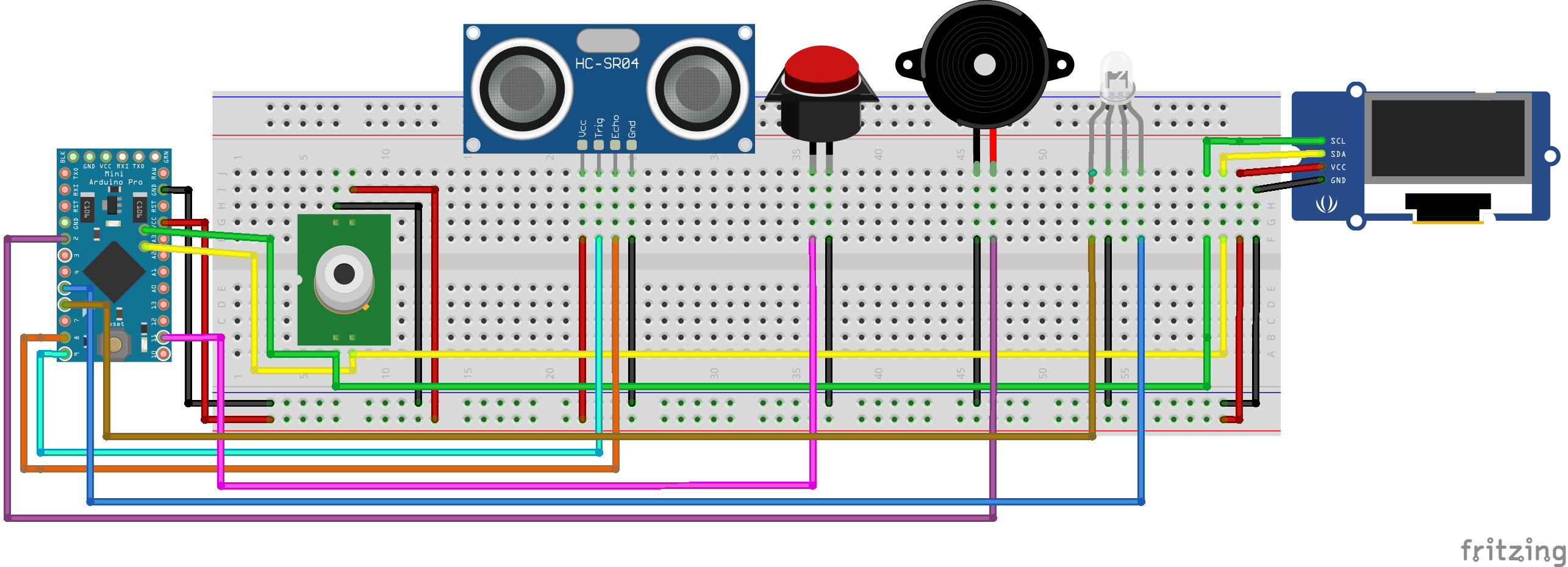
The above image is the circuit diagram for our project. I will briefly explain how things work here.
The OLED and MLX90614 sensor both of them communicate with I2C protocol with the Arduino. We only have to connect 4 pins for each of the components they are, VCC, GND, SDA & SCL. We have connected SDA to A4 and SCL to A5. The pins of ultrasound sensors are as follows Trigger to A9 and Echo to A8. One leg of the button is connected to A11. The button pin is set to input with pull-up register enabled. A pullup register is used to avoid floating pins. The logic of floating pin is random so Arduino may detect unwanted noise. One leg of the buzzer is connected to A2. A logic HIGH will give us the beep sound.
I have used common cathode RGB led here i.e. there is a common ground and logic HIGH will switch on the led. In this project, I have used only Red and Green led legs. Green is connected to A5 and Red to A6.
SOFTWARE FLOWCHARTThis is the basic flow of the code that was written in C++ on Arduino IDE.
After the Power is given to the Arduino pro mini it starts up the code. All the library is included and then the variables are defined. Functions are also defined in this block. After this, the Initialization or void setup() function begins. Here we start up the serial terminal if you want to debug the code or else you can comment on it. Then all the pins are defined as Input or Output. The OLED screen is also clear so that we can use a blank screen.
The Arduino now enters in a void loop(). This loop runs forever. First, we display the Main Menu on the OLED screen. Then the code checks if the button is pressed or not. If the button is pressed the reading will change between degree Fahrenheit and degree Celcius.
Simultaneously, If the user has placed his head in front of the sensor the ultrasound sensor senses it. If the distance is within the threshold it will get data from the MLX90614 sensor via I2C. And will display the temperature on the screen. The led will also light up according to the temperature. We can hear a beep from the buzzer indicating that the temperature is displayed on the screen.
The led light changes under different conditions.
Green -> Temp under 99 degrees Fahrenheit (Indicating OK condition)
Orange -> Temp between 99 to 102 degrees Fahrenheit (Indicating FEVER)
Red -> Temp above 102 degrees Fahrenheit (Indicating HIGH Fever)
The code is attached below and I have also added comments for references.
The STL file for the case is attached below. I could only print the lid to handle all my components. My 3d printer broke down and that's the reason why I could not print my box to hold electronics.
If you have any questions or require any help in any project feel free to message me here. I am happy to entertain all doubts


_3u05Tpwasz.png?auto=compress%2Cformat&w=40&h=40&fit=fillmax&bg=fff&dpr=2)
Comments
Please log in or sign up to comment.