


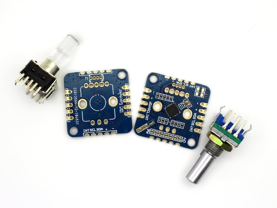
Hardware components | ||||||
 |
| × | 1 | |||
 |
| × | 1 | |||
This is the upgraded version of our original project: https://hackaday.io/project/27611-i2c-encoder. We added some new improvements. Most important are the support of the RGB encoders, extension of the addressing to 7bit and a new shape
The project is now available on Kickstarter! http://kck.st/2Kh6Kta
DetailsAfter the first version of the I2C encoder we collected all the suggestions and we made this new upgraded version!
The project is not ready yet, we need to finish and test the firmware part.
New features:
- It's support the standard rotary encoder and the RGB encoder
- It's possible to set all the 7bit of the I2C address trough a SMD jumper
- Dimension of 25x25mm or 0.98x0.98in
- With the castellated holes is possible to connected several boards on the 4 sides
- Possibility to solder the pull-up resistor on the I2C bus
- 3 General Purpose pins. (GP pins)
- 256byte of internal EEPROM divided in the 2 bank of 128 byte
- Advanced configuration respect the first version
Details:
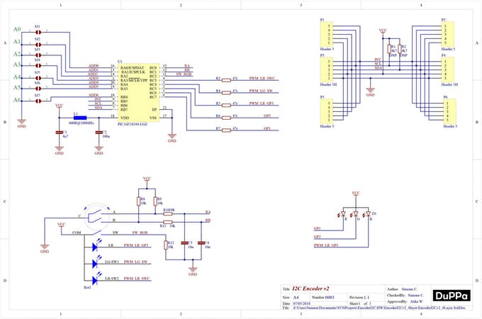
This new version is powered by the PIC16F18344. Respect to the MCU on the first version, it has more GPIO and the EEPROM memory.
The new design of the board support both the standard encoders and the illuminated RGB encoders.
Moreover, there are the castellated holes on all the 4 sides of the PC, in this way will be possible to connect multiple board by soldering them.
There are also 3 configurable GPIOs organized with the same footprint of a RGB LED. They are called GP1 GP2 and GP3.But in case you are using the RGB encoder, the configurable GPIOs are only 2: GP1 and GP2.
GPIO configuration:- PWM: In this way you can add a RGB LED
- OUTPUT: You can use the pins as standard digital output.
- Analog: The pins are connected to the internal ADC of the PIC. In this way you can add sensors or potentiometer
- Input: You can use the pins as standard digital input. Plus you can configure also the interrupt on the edges
The INT pin is an open-drain output, and it's used to send an interrupt to the master.
The interrupt is active low, and have multiple sources where it's possible to mask.
Interrupt source:- Encoder push button pressed
- Encoder push button released
- Encoder is moved clockwise
- Encoder is moved counterclockwise
- The counter value reach the maximum value
- The counter value reach the minimum value
- The GP pins changed when configure as digital input
This is the preliminary version of the internal registers:
Now it is possible to configure the Counters register to work as int 32bit or as float numbers IEEE 754.There is also the possibility to set the Increment step, which meas that it's possible to set of how much the Counter Value is increased or decreased at every encoder step.


Comments